
All figures (15)

Fig. 4. (a) A camera checker board image and (b) the corresponding projector checker board image. 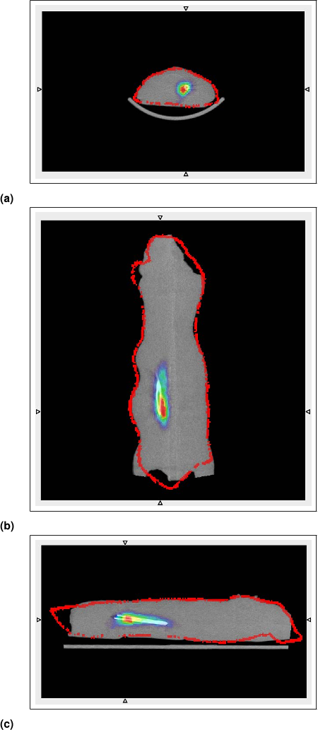
Fig. 14. (a) The tranverse, (b) coronal and (c) sagittal views of the overlaid FMT (rainbow) and CT (grey) images. The color line plots the FMT image boundary. The arrows indicate the plotted section position. 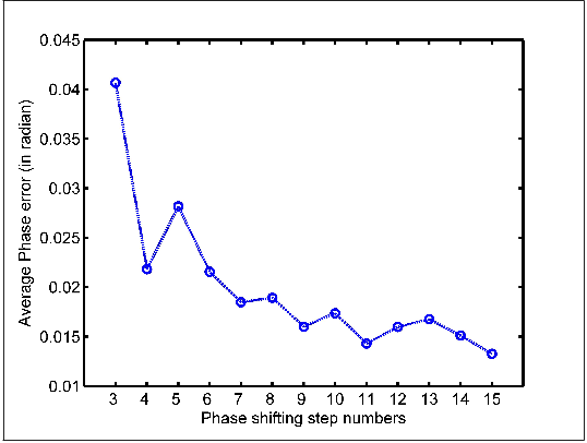
Fig. 5. Phase errors caused by non-linearity of projectors with different fringe pattern numbers. 
Fig. 6. (a) Alignment of the two point clouds of the calibration bar and (b) the cross section compared with the ground truth. 
Table 1. Measured height of the step object (mm) 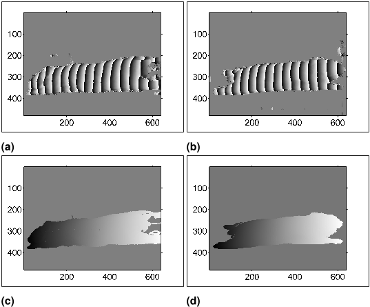
Fig. 8. (a,b) The wrapped and (c,d) the unwrapped phase map for webcam 1 (a,c) and webcam 2 (b,d). 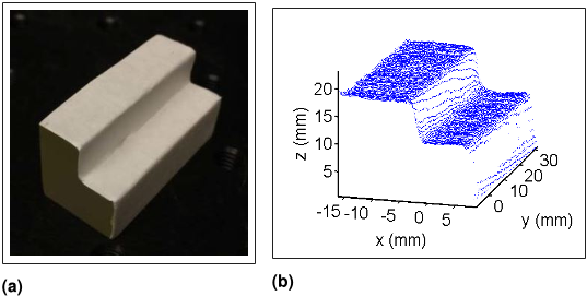
Fig. 10. (a) The picture and (b) the reconstructed results of a step object. 
Fig. 7. (a) Photograph of a mouse shaped agar phantom, (b) one fringe pattern captured by webcam 1 and (c) by webcam 2. 
Fig. 9. The mouse surface point cloud. 
Table 2. Comparision Between Different Surface Measuring Methods 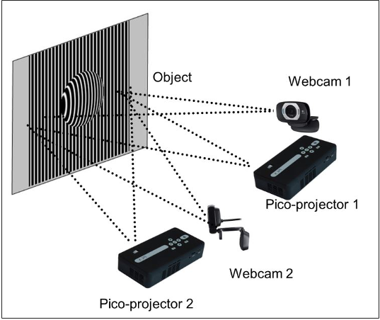
Fig. 1. Schematic of the surface extraction system. 
Fig. 11. Comparison between the surface data obtained from the webcam-projector pair and the CT data of (a) the whole surface and (b) a transverse section at x = 60 mm. 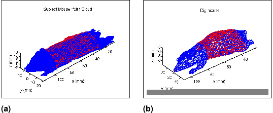
Fig. 12. 932 corresponding points (red dots) between the (a) extracted mouse surface point cloud and (b) the Digimouse. 
Fig. 3. Photograph of the FMT imaging system with the two pairs of pico-projector and webcam. 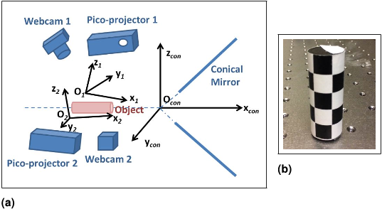
Fig. 2. (a)Three coordinate systems in the FMT imaging system and (b) photograph of the calibration bar.


