
All figures (11)

Figure 7: (a) Temperature field of the outer surfaces of the electrode, (b) Temperature profile 436 along a vertical line cutting through a protuberance. Results obtained during the quasi-437 stationary regime at t=22.2 s. 438 
Figure 2: Cross-section of the computational domain. 281 
Figure 6: (a) Velocity vectors (3D) inside a protuberance. (b) Turbulent to molecular viscosity 401 ratio in a vertical cross-section of a protuberance. 402 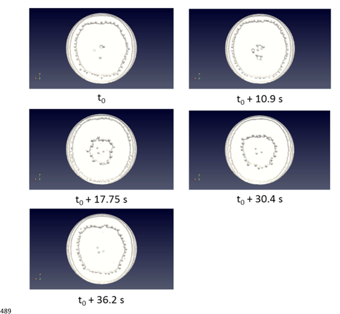
Figure 10: Temporal evolution of the protuberance distribution at the tip of the electrode. 490 
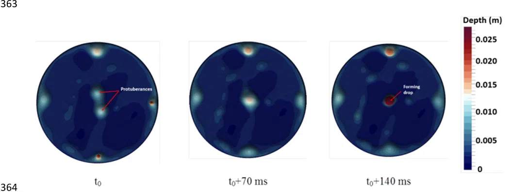
Figure 4: Depth of protuberances formed from the liquid film. 365 ![Figure 5: Formation and detachment of a drop observed experimentally [6] (top row) 376 and predicted by the numerical model (bottom row). 377](/figures/figure-5-formation-and-detachment-of-a-drop-observed-3lqhxps8.png)
Figure 5: Formation and detachment of a drop observed experimentally [6] (top row) 376 and predicted by the numerical model (bottom row). 377 
Figure 1: Schematic representation of the vacuum arc remelting process. 50 
Figure 11: (a) Temperature field of the outer surfaces of the electrode, (b) Temperature 534 profile along the electrode central axis. Results obtained at t = 662 s 535 
Figure 9: (a) Example of a calculated capillary bridge (drip-short). (b) Velocity vectors (3D) in 483 the bridge.(c) Turbulent to molecular viscosity ratio in a vertical cross-section of the bridge. 484 
Figure 3: Vertical cross-section of the computational domain used for the simulation of 341 the Ti-6Al-4V electrode. 342 
Figure 8: Vertical cross-section of the computational domain used for the simulation of the 459 maraging steel electrode. 460


![Figure 5: Formation and detachment of a drop observed experimentally [6] (top row) 376 and predicted by the numerical model (bottom row). 377](/figures/figure-5-formation-and-detachment-of-a-drop-observed-3lqhxps8.webp)


