scispace - formally typeset
Search or ask a question
Journal ArticleDOI

6D interaction control with aerial robots: The flying end-effector paradigm

TL;DR: A novel paradigm for physical interactive tasks in aerial robotics allowing reliability to be increased and weight and costs to be reduced compared with state-of-the-art approaches is presented.
Abstract: This paper presents a novel paradigm for physical interactive tasks in aerial robotics allowing reliability to be increased and weight and costs to be reduced compared with state-of-the-art approac...

Summary (3 min read)

INTRODUCTION

  • Direct physical interaction of a robot with its environment is a vast and continuously growing field of research with several relevant applications.
  • A drawback of this solution is that typical aerial platforms are underactuated and therefore it is impossible to independently control the 6D (position plus orientation) dynamics of the end-effector.
  • In Rajappa et al. (2017), the authors, by exploiting both a wrench estimation and a ring of eight contact sensors, proposed a control able to separate human interaction forces from additional disturbances as wind and parameter uncertainties.

System Modeling

  • The authors consider as aerial robot a fully actuated aerial vehicle equipped with an arbitrarily mounted end-effector tool.
  • Selecting an alternating sign of α for every other propeller in (4) allows for the full actuation of the aerial vehicle.

Controller

  • In this section the authors describe the single components of the controller.
  • The control framework is based on an outer loop admittance control and an inner loop full-pose controller .
  • The state of the aerial robot is estimated by a Unscented Kalman Filter (UKF) that fuses the Inertial Measurement Unit (IMU) acceleration and angular velocity measurements with the position and orientation from a pose sensor (in their case a motion capture system, which could be easily replaced with an onboard camera using a Perspectiven-Point (PnP) algorithm).
  • The interaction torques and forces are estimated by a wrench observer.

Pose Controller

  • The authors will therefore only summarize the controller here.
  • The block diagram of Figure 3 shows the control scheme architecture.
  • Euler angles are prone to singularity issues.

Contact Wrench Estimation

  • To this aim, a force/torque sensor could be mounted on the robot’s tooltip, which is usually capable to provide a reliable measure, but this solution increases both the cost and the weight of the robot.
  • Thus, in this paper, the hybrid approach already proposed in Tomic et al. (2017), has been followed.
  • More in detail, the acceleration based observer proposed by Yüksel et al. (2014a) is adopted in order to estimate the external interaction forces on the robot CoM, fR, while the external torques, τ RR are obtained by exploiting a momentum-based observer (De Luca and Mattone (2005)).
  • The choice of the matrix KI is a trade-off between the convergence rate and the filtering properties of the observer: greater values of the gains allow faster convergence while smaller values allow to filter the high-frequency noise.
  • The resulting force and torque profiles are presented in Figure 4.

Interaction wrench compensation

  • To achieve optimal results of the admittance filter a highly stiff low-level tracking is desired.
  • Accepted for The International Journal of Robotics Research 2019 (17) and, thus, the same stability properties hold.
  • Otherwise, under the trivial assumption that the interaction wrench is bounded, the wrench estimation error can be viewed as a bounded term as well.
  • Moreover, if the interaction wrench is constant, the wrench estimation error is convergent to zero, and, thus, after it vanishes also the tracking error will converge to zero as well.

Hardware

  • The Tilt-Hex robot is a LAAS-CNRS in house developed fully actuated aerial robot.
  • All used structural components are either off-the-shelf available or 3D printable by a standard fused deposition modeling printer.
  • The total mass, including a 2.2 Ah LiPo-battery and the rigid end-effector accumulates to 1.8 kg.
  • To retrieve the Tilt-Hex’s pose estimation and its derivatives the aerial robot contains a standard IMU with accelerometers and gyroscopes, providing the sensor information at 500 Hz.
  • The on-board and external sensor information are fused by an UKF state estimator, providing full state estimation at 500Hz.

Software

  • The full control framework described above has been implemented in a Matlab Simulink environment to boost a fast development.
  • For safety the aerial robot is currently connected via a serial connection (RS232) with the desktop machine, which transmits the desired propeller spinning velocities to the TiltHex and the actual propeller spinning velocity, IMU data, all at 500 Hz, and further status updates, e.g., safety checks, battery status with a lower frequency to the base PC.
  • The MoCap measurements (100Hz) are fused via a UKF state estimator with the IMU measurements (500Hz) thus obtaining a full state estimate at 500Hz.

Experimental Results

  • To present the capabilities and limits of the control framework a broad spectrum of different experiments has been conducted - the interested reader is as well referred to the attached multimedia data.
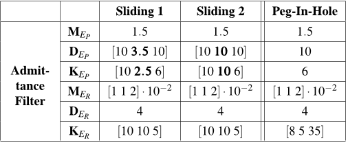
  • Firstly, the authors will present a bench of experiments demonstrating the physical property shaping capabilities of the outer loop admittance filter.
  • Secondly, the authors show a hard contact and sliding of the off-centered tool-tip while making use of the afore presented physical property shaping to fulfill a desired task.
  • Thirdly the authors present a challenging flying peg-in-hole task.
  • Accepted for The International Journal of Robotics Research 2019.

Physical properties shaping

  • The authors will now experimentally test and demonstrate the physical property shaping capabilities of the outer loop admittance filter with respect to the end-effector tool-tip.
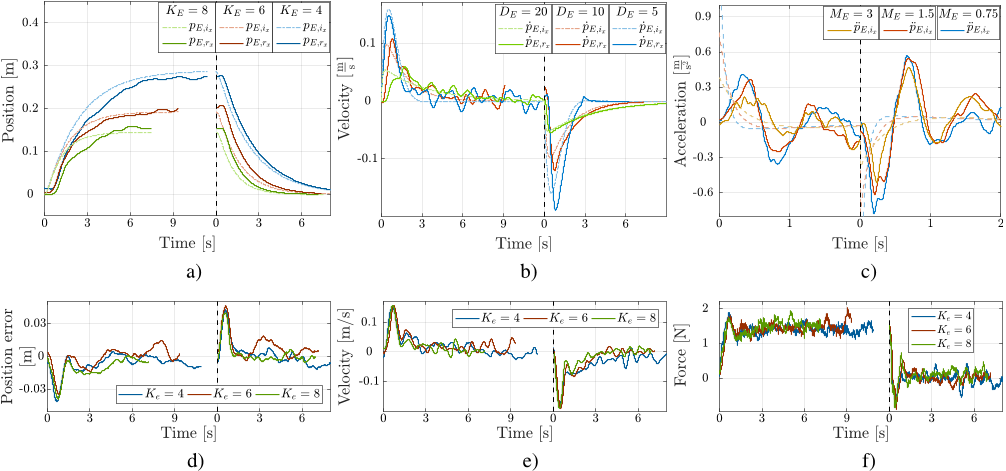
  • By exerting a step-like force profile on the aerial robot the authors will show that they can achieve a large variety of desired massspring-damper behaviors.
  • To get a better insight of the effect of a changed damping parameter the authors now compared the ideal msd-system velocity ṗE,i with the real reference velocity output ṗE,r in Figure 7b.
  • This behavior is explained by the first order low-pass dynamics of the wrench observer.

Sliding on Surface

  • The authors conducted a hard contact between the tool-tip of the rigid end-effector and a tilted wooden surface .
  • First the desired trajectory approaches without contact from an initial position to a position 0.14m above the surface (approaching phase).
  • To reduce stick slip effects between the tool-tip and the surface during the sliding-phase the desired orientation of the tool-tip is tilted forward by (θR,d = 7.5◦).
  • The fourth plot (8d) presents the difference between the components of the preplanned desired position trajectory and the admittance filter output (pR,d − pR,r).
  • During the approaching phase the aerial robot’s desired pitch orientation changes from θ = 0◦ to θ = 7.5◦ and remains constant hereafter.

Peg-In-Hole task

  • The experimental setup of the peg-in-hole task employs a 15◦ tilted standing funnel.
  • In detail, the desired end-effector trajectory first follows a translation along xW and stops 0.16m above the funnel .
  • The experimental results are reported in Figure 12.
  • The torque causes the admittance filter to adapt the reference pitch orientation θR,r with respect to the desired angle θR,d until the tip can be fully inserted into the funnel.

Multi contact sliding

  • The last conducted experiment is inspired by common industrial tasks like inspection with contact, surface polishing or welding where, while translating, a particular force application on a surface is needed.
  • Then, the second phase starts with applying a constant force against the ledge, in direction yW (.
  • The end-effector is now in contact with three sides and cannot translate anymore.
  • The reference pR,r, desired pR,d and actual positions pR are depicted in Figure 14a, showing first, an error free matching of pR,pR,r and pR,d in the absence of a contact force and second, a divergence between pR,d ,pR,r during contact, while the end-effector pR still perfectly tracks pR,r.
  • In contrast to the first three experiments, aerodynamic effects between the aerial robot and the solid surface are observed, resulting in a mismatches between the estimated and measured forces and torques, see Figure 14c.

Summary

  • The authors tackled the issue of precise 6D aerial physical interaction with the environment.
  • The authors utilized a novel fully actuated aerial platform, namely the Tilt-Hex allowing to independently control the linear and the angular acceleration.
  • Hereby, the platform can instantaneously counteract any wrench during the contact with the environment.
  • An outer loop admittance control scheme steers the system to a desired impedance behavior only during the presence of an interaction wrench by computing a suitable reference trajectory.
  • An advanced set of experiments was performed to show the full capabilities of the platform.

Did you find this useful? Give us your feedback

Figures (16)

Content maybe subject to copyright    Report

HAL Id: hal-02383394
https://hal.laas.fr/hal-02383394
Submitted on 27 Nov 2019
HAL is a multi-disciplinary open access
archive for the deposit and dissemination of sci-
entic research documents, whether they are pub-
lished or not. The documents may come from
teaching and research institutions in France or
abroad, or from public or private research centers.
L’archive ouverte pluridisciplinaire HAL, est
destinée au dépôt et à la diusion de documents
scientiques de niveau recherche, publiés ou non,
émanant des établissements d’enseignement et de
recherche français ou étrangers, des laboratoires
publics ou privés.
6D interaction control with aerial robots: The ying
end-eector paradigm
Markus Ryll, Giuseppe Muscio, Francesco Pierri, Elisabetta Cataldi, Gianluca
Antonelli, Fabrizio Caccavale, Davide Bicego, Antonio Franchi
To cite this version:
Markus Ryll, Giuseppe Muscio, Francesco Pierri, Elisabetta Cataldi, Gianluca Antonelli, et al.. 6D
interaction control with aerial robots: The ying end-eector paradigm. The International Journal
of Robotics Research, SAGE Publications, 2019, 38 (9), pp.1045-1062. �10.1177/0278364919856694�.
�hal-02383394�

6D Interaction Control with Aerial
Robots: The Flying End-Effector
Paradigm
Accepted for The International Journal of
Robotics Research 2019
Preprint version,
final version at
https://journals.sagepub.com/loi/ijra
Markus Ryll
1
, Giuseppe Muscio
2
, Francesco Pierri
2
, Elisabetta Cataldi
3
, Gianluca
Antonelli
3
, Fabrizio Caccavale
2
, Davide Bicego
1
and Antonio Franchi
1
Abstract
This paper presents a novel paradigm for physical interactive tasks in aerial robotics allowing to increase reliability and
decrease weight and costs compared to state of the art approaches. By exploiting its tilted propeller actuation, the robot
is able to control the full 6D pose (position and orientation independently) and to exert a full-wrench (force and torque
independently) with a rigidly attached end-effector. Interaction is achieved by means of an admittance control scheme
in which an outer loop control governs the desired admittance behavior (i.e., interaction compliance/stiffness, damping,
and mass) and an inner loop based on inverse dynamics ensures full 6D pose tracking. The interaction forces are
estimated by a IMU-enhanced momentum based observer. An extensive experimental campaign is performed and four
case studies are reported. Firstly, a hard touch and slide on a wooden surface, named sliding surface task. Secondly, a
tilted peg-in-hole task, i.e., the insertion of the end-effector in a tilted funnel. Then an admittance shaping experiment in
which it is shown how the stiffness, damping and apparent mass can be modulated at will. Finally, the fourth experiment
is in charge of showing the effectiveness of the approach also in the presence of time-varying interaction forces
Keywords
Aerial robotics, Aerial physical interaction, Aerial Manipulation
INTRODUCTION
Direct physical interaction of a robot with its environment
is a vast and continuously growing field of research with
several relevant applications. Industrial case studies have
been object of massive research, see, e.g., Villani and
De Schutter (2008) for an introductory reading. Recently,
the use of aerial robotic platforms, possibly equipped with
an arm, came prominently into focus. Aerial robots offer
a nearly unlimited motion space and can be exposed in
dangerous or poisonous environments. Along this line,
aerial robots have been recently exploited in operations
such as, e.g., transportation (Fink et al. (2011)), structure
assembly, object grasping (Augugliaro et al. (2014)), and
wall inspection (Fumagalli et al. (2012)), requiring both
autonomous flight competences and physical interaction
capabilities; the latter being a particularly challenging task
due to the complexity of aerodynamics especially when
the vehicle is close to surfaces and intrinsic instability of
almost all the aerial robotic platforms.
To perform physical interaction, aerial robots are either
equipped with a rigid tool or an n degree of freedom (DoF)
robotic arm. In the first case, the tool is rigidly fixed to
the airframe, see, e.g., Gioioso et al. (2014b); Augugliaro
et al. (2014); Y
¨
uksel et al. (2014b); Nguyen and Lee (2013);
Gioioso et al. (2014a). A drawback of this solution is that
typical aerial platforms are underactuated and therefore it is
impossible to independently control the 6D (position plus
orientation) dynamics of the end-effector. This limits the
potential use cases and also creates stability issues. In fact, it
has been shown that in the presence of interaction with points
of the airframe different from the vehicle’s center of mass
(CoM) the internal dynamics of underactuated multi-rotors
is not guaranteed to be stable, and it is, in general, neither
easy to stabilize nor practical for real applications (Nguyen
and Lee (2013)).
The second possibility is to attach an n-DoF robotic arm
to the aerial platform (Muscio et al. (2016, 2017); Baizid
et al. (2016); Kim et al. (2013); Tognon et al. (2017)),
a solution which aims at overcoming the underactuation
of the end-effector dynamics by exploiting the increased
number of actuators provided by the arm. In this way, a fully
actuated 6D force control at the end-effector side becomes
possible (Yang and Lee (2014)). However, this solution
comes with several drawbacks as well, which are mentioned
in the following:
i) a robotic arm strongly decreases the payload and flight
time due to its own weight;
ii) the system is much more complex from a mechanical
point of view than a single airframe with a rigid tool and,
thus, it is more expensive to build and also requires more
maintenance and repairing costs across its operational life;
1
LAAS-CNRS, Universit
´
e de Toulouse, CNRS, Toulouse, France,
2
University of Basilicata, School of Engineering, via dell’Ateneo Lucano,
10, Potenza, Italy,
3
University of Cassino and Southern Lazio, Via Di Biasio 43, 03043
Cassino, Italy
Corresponding author:
Antonio Franchi, LAAS-CNRS, Universit
´
e de Toulouse, CNRS, Toulouse,
France.
Email: antonio.franchi@laas.fr
Preprint, final version at https://journals.sagepub.com/loi/ijra

2 Accepted for The International Journal of Robotics Research 2019
iii) lateral forces in body frame, which cannot be provided
by the aerial platform itself, have to be generated through the
dynamical/inertial coupling between the arm and the aerial
robot: the proper mastering of the dynamical coupling is
something that has to be necessarily exploited in order to
get the sought benefits in terms of 6D force control. This, in
turn, requires the knowledge of the precise dynamical model
and a very accurate measurement of the system inputs and
states (position, orientation, linear and angular velocities).
As a matter of fact, these requirements are extremely hard to
achieve in real world conditions (especially the former). For
this reason, kinematic-only approaches have been preferred
for real world validations, see e.g., Muscio et al. (2016,
2017), at the expense of losing the main benefits for which
the manipulator was introduced.
As a byproduct, the use of such complex systems has
been exploited in real world so far only for basic interaction
tasks such as, e.g., pick and place, vertical insertion,
and pull/pushing of constrained objects like drawers (Kim
et al. 2015). At the best of our knowledge, more complex
interactions required in real world like: a) peg in-hole
with non-vertical orientation, b) position-force control for
sliding on surfaces, and, more in general, c) an accurate
shaping of the full 6D force/moment interaction of the end-
effector with the environment; have not yet been successfully
demonstrated in real world in state-of-the-art systems.
Summarizing, standard flying platforms are underactuated
and, thus, incapable of 6D end-effector force control. On the
other side, using a full manipulator up in the air to perform
the sought 6D end-effector force control is often excessively
complex and may introduce more problems than benefits.
To solve all these problems at once and finally achieve
the sought full 6D force control of the aerial interaction,
we propose a novel paradigm which we named the Flying
End-Effector. The concept is based on the ascertainment
that the overall mission goal is to achieve 6D interaction
with an end-effector. While in ground robotics the end-
effector must be actuated by a manipulator with at least six
degrees of freedom (DoF), in the aerial robotics case there
is no necessity to bring up to the air a full manipulator
together with the end-effector. What is instead needed is
that the aerial robot possesses the minimal requirements
to perform such interaction with a rigidly attached end-
effector. In order to achieve such requirements, we propose
to use a multi-rotor robot with non-collinear fixedly-tilted
propellers (NCFTP) instead of the more common collinear
fixedly-tilted propeller (CFTP) architectures (Ryll et al.
(2016)). In NCFTP platforms, which appeared in the robotics
literature only recently (see, e.g., Rajappa et al. (2015);
Voyles and Jiang (2014); Brescianini and D’Andrea (2016);
Park et al. (2016)), the full-actuation is achieved by a more
general propeller position and orientation. The difference
between the underactuated platform and NCFTP platforms
is that, in the former approach, all the propellers have
the same orientation while, in the latter approach, every
propeller orientation is different. The NCFTP approach is,
thus, able to control independently the translational and
angular acceleration when unconstrained, or any of the six
components of the exerted wrench when in contact, thus
allowing full and dexterous 6D force control, which makes
them much more suited for physical interaction tasks than
standard CFTP platforms.
Another solution to obtain full-actuation consists of
actively tilting the whole propeller groups (Ryll et al. (2016,
2015); Long and Cappelleri (2013)), a solution which is
called thrust vectoring or tilting propeller. This solution
however is subject to the same drawbacks of the solutions
employing a manipulator arm, since they require extra
actuation, mechanical complexity, and weight. Furthermore,
they cannot in general guarantee instantaneous disturbance
rejection or fast force exertion since the propellers might
have to be re-oriented, which again takes some non-
negligible time.
A critical issue for aerial robot interaction control is the
measurement of the interaction wrench. A reliable solution
is the adoption of force/torque sensors, such as in Antonelli
et al. (2016) where the wrench measurement of a wrist
mounted sensor of an aerial manipulator is fed to an
admittance filter. Use of force/torque sensor increases the
cost and the weight of the aerial platform, thus alternative
solutions based on wrench estimators have been proposed
in the last years. In Y
¨
uksel et al. (2014a) a Lyapunov-
based nonlinear observer is proposed for estimating the
external wrenches applied on a quadrotor, while in Tomic
and Haddadin (2014) a hybrid estimation is proposed, using
the linear acceleration for directly computing the interaction
forces and a momentum based observer for estimating
the interaction torques. In Tomic et al. (2017) the same
authors propose a more refined hybrid estimation, where
the estimated forces are not simply computed by the model
but are obtained via a first-order stable filter, similar to
the solution proposed in Y
¨
uksel et al. (2014a). In Rajappa
et al. (2017), the authors, by exploiting both a wrench
estimation and a ring of eight contact sensors, proposed
a control able to separate human interaction forces from
additional disturbances as wind and parameter uncertainties.
In Tagliabue et al. (2016) as well an admittance control
framework is used for collaborative transportation of objects
by using underactuated aerial robots, an approach which is
theoretically analyzed and refined in Tognon et al. (2018) by
demonstrating its stability and the fundamental role of the
internal force in such control scheme.
A preliminary (6-pages long) version of this work has been
presented in a conference version (Ryll et al. (2017)). With
respect to Ryll et al. (2017), in this paper i) we provide much
more details for all considered aspect; ii) we consider an
improved solution for the wrench estimate that exploits also
the linear acceleration measurements provided by the IMU;
iii) the position and force tracking quality has been largely
improved; iv) the physical property shaping capabilities of
the admittance filter are thoroughly tested and explained
and v) a very broad range of experiments is performed and
discussed; in particular, the case of sliding on a surface
with a tilted orientation, the peg-in-hole experiment, and the
admittance shaping tests and sliding in contact with two
ledges have been conducted.
Concluding this introduction, in the following we
summarize the main contributions (but not all) of this work:
1) we propose and show the practicability through real
experiments, of a completely new aerial physical interaction
paradigm: the 6D flying end-effector. We believe that this
Preprint, final version at https://journals.sagepub.com/loi/ijra Accepted for The International Journal of Robotics Research 2019

6D Interaction Control with Aerial Robots: The Flying End-Effector Paradigm 3
Figure 1. The Tilt-Hex (NCFTP aerial platform with tilted
propellers in-house developed at LAAS-CNRS) with the rigidly
attached end-effector. Notice how the interaction takes place far
away and off-centered from the vehicle CoM. The picture is
taken right after a Peg-In-Hole task was successfully performed.
paradigm will pave the way to a novel aerial system concept
which outperforms currently adopted solutions for aerial
manipulation and physical interaction in terms of capability,
reliability, complexity and costs.
2) we propose a specific integration of known robotic
algorithms, achieving both motion and interaction control
as well as external wrench estimation, in a thoroughly
conceived architecture and show how the integrated system
can work with a minimal sensor suite (pose sensor plus IMU)
not even needing a force sensor in its basic configuration
the addition of more sensors, if available, being anyway
straightforward.
3) in support of the aforementioned features, we show
experiments that are the first of their kind in aerial robotics:
fully impedance shaping in 6D, peg-in-hole with tilted
holes, sliding on tilted surfaces. Moreover, in order to
show the effectiveness of the wrench estimate, a forth
experiment, consisting on sliding in contact with two ledges
on a surface mounted on an ATI45 force/torque sensor, has
been conducted in such a way to exert variable forces and
torques on the end-effector. The wrench estimator results
are compared with the measures obtained by the sensor. The
experiments are designed to clearly show the versatility and
the robustness of the proposed approach to the environmental
uncertainties.
The paper is organized as follows. First a generic model
for NCFTP aerial systems is introduced and afterwards we
model the proposed NCFTP platform, named Tilt-Hex. Then
the complete admittance control framework is presented as
well as its components, namely the inner loop geometric pose
controller, the wrench observer and the outer loop admittance
filter. Then we present the hard-/software architecture and the
experimental evaluation. Finally, we conclude the paper with
a summary of the results and an outline of future works.
Remark It is important to mention that the theory and the
architecture proposed in this paper is very general and works
seamlessly with any NCFTP platform other than the one used
in particular here.
System Modeling
We consider as aerial robot a fully actuated aerial vehicle
equipped with an arbitrarily mounted end-effector tool. The
presented physical interaction framework is generic for any
fully actuated system able to track a full-pose trajectory
with the end-effector. We shall start with the generic parts
of the modeling and present afterwards the instantiation of
this general model for the NCFTP hexarotor used in the
experiments.
General Modeling Let us consider the following coordinate
frames (see Figure 2):
Inertial world frame F
W
, whose axes (unit vectors)
and origin are indicated with {x
W
,y
W
,z
W
} and O
W
,
respectively;
Body frame F
R
: O
R
{x
R
,y
R
,z
R
}, attached to the
robot and with origin O
R
in the CoM of the aerial
vehicle with the end-effector;
End-effector frame F
E
: O
E
{x
E
,y
E
,z
E
}, attached to
the robot end effector and with origin in the interaction
point O
E
.
For a generic vector υ, the notation υ
?
(with ? = R,E)
denotes that the vector υ is expressed in frame F
?
. If the
superscript is omitted it means that the vector is expressed in
inertial frame.
The position of O
R
expressed in F
W
is denoted by p
R
R
3
, while the position of O
E
in F
W
and in F
R
are denoted by
p
E
R
3
and p
R
E
R
3
, respectively, where p
R
E
is constant over
time. Analogously, let us denote with R
R
SO(3) and R
E
SO(3) (where SO(3) = {A R
3×3
|AA
T
= I det A = 1})
the rotation matrices expressing, respectively, the orientation
of frame F
R
and F
E
with respect to the inertial frame F
W
.
Moreover, R
R
E
SO(3) denotes the constant rotation matrix
expressing the orientation of F
E
with respect to F
R
. Finally
let us denote as ω
ω
ω
R
R
R
3
and ω
ω
ω
E
E
R
3
the angular velocities
of F
R
and F
E
with respect to F
W
expressed, respectively,
in frame F
R
and F
E
. Thus, the orientation kinematics of the
robot and the end effector are then expressed by
˙
R
R
= R
R
[ω
ω
ω
R
R
]
×
(1)
˙
R
E
= R
E
[ω
ω
ω
E
E
]
×
, (2)
respectively, where []
×
SO(3) represents the skew
symmetric matrix (Siciliano et al. (2009)) associated to
vector R
3
.
Using the Newton-Euler formalism, the equation of
motion of the aerial robot can be expressed as
m
¨
p
R
J
˙
ω
ω
ω
R
R
=
mge
3
ω
ω
ω
R
R
×Jω
ω
ω
R
R
| {z }
g(ω
ω
ω
R
R
)
+
f
τ
τ
τ
R
+
f
R
τ
τ
τ
R
R
(3)
where m and J R
3×3
represent the robot mass and its inertia
matrix with respect to O
R
and expressed in F
R
, respectively,
g is the gravitational acceleration, f R
3
and τ
τ
τ
R
R
3
are
force and torque inputs, while f
R
and τ
τ
τ
R
R
are the external force
and torque on the robot CoM due to the force and torque
exerted by the environment on the end-effector.
Preprint, final version at https://journals.sagepub.com/loi/ijra Accepted for The International Journal of Robotics Research 2019

4 Accepted for The International Journal of Robotics Research 2019
Figure 2. Schematic view of important frames and vectors of
the Tilt-Hex with the rigidly attached end-effector. The zoomed
propeller group shows further vectors needed to model the
system.
Remark It is worth noticing that, as usual in aerial robotics
field, in (3) the translational dynamics is expressed in the
frame F
W
, while the rotational dynamics is expressed in the
frame F
R
.
Tilt-Hex Without loss of generality for any fully actuated
aerial platform, we will now derive (3) for the NCFTP
platform used in the later presented experiments. The
NCFTP platform is based on a hexarotor structure, with
propellers equally-spaced and equidistant from O
R
in the
x-y-plane of F
R
. Full actuation is achieved by rigid
adapters, tilting every single motor-propeller combination
(see Figure 1 and 2). Let us consider 6 frames F
P
i
, i = 1 ...6
where O
P
i
coincides with the center of rotation of the i-th
propeller group (see Figure 2). The orientation of F
P
i
with
respect to F
B
is represented by the rotation matrix
R
R
P
i
= R
z
((i 1)
π
3
)R
x
((1)
i1
α)R
y
(β ), i = 1...6. (4)
The inclination of the i-th motor-propeller group with
respect to F
R
is defined by the constant parameters α and
β . The selection of α and β decides the maximum lateral
forces with the cost that higher lateral forces result in higher
internal forces and therefore a waste of energy (Rajappa et al.
(2015)). Selecting an alternating sign of α for every other
propeller in (4) allows for the full actuation of the aerial
vehicle.
The i-th motor-propeller group’s position with respect to
O
R
can be defined as
p
R
P
i
= R
z
((i 1)
π
3
)l +R
x
((1)
i1
α)R
y
(β )d, i = 1 ...6
(5)
where d is the vector from the center of the tilting rotation to
the center of the motor-propeller group O
P
i
, and l is the vector
from O
R
to the center of the tilting rotation (see Figure 2).
As well known, a spinning propeller generates a thrust
force and a drag moment in O
P
i
. In a good approximation
both can be modeled by utilizing the signed squared of the
spinning velocity as
f
R
i
= c
f
u
i
R
R
P
i
e
3
, i = 1 . . . 6 (6)
and
τ
τ
τ
R
i
= (1)
i1
c
τ
u
i
R
R
P
i
e
3
, i = 1 . . . 6 (7)
Table 1. Overview of most symbols used in this paper. If
constant through all experiments a value is presented as well.
Definition Symbol Value
Inertial world frame with origin O
W
and axes {x
W
,y
W
,z
W
} F
W
Robot body frame with origin O
R
and axes {x
R
,y
R
,z
R
} F
R
End effector frame with origin O
E
and axes {x
E
,y
E
,z
E
} F
E
Symbols that can assume the values W,R, or E ?,
Position of O
in F
W
p
Velocity of O
in F
W
v
Rotation matrix expressing the orientation of F
w.r.t. F
?
R
?
Rotation matrix expressing the orientation of F
w.r.t. F
W
R
Angular velocity of F
w.r.t. F
W
, expressed in F
ω
ω
ω
Reference position expressed in F
W
p
R,r
Reference rotation matrix R
R,r
Desired position expressed in F
W
p
R,d
Desired rotation matrix R
R,d
Actuation wrench expressed in F
W
w
Real external wrench on the EE in F
W
w
E
Observed (estimated) external wrench on the EE in F
W
ˆ
w
E
Observed (estimated) external wrench on the robot in F
W
ˆ
w
R
Tilting angle (around x
P
i
) of the i
th
prop. group α
i
35
Tilting angle (around y
P
i
) of the i
th
prop. group β
i
10
i
th
propeller blade spinning frequency about z
P
i
(in Hz)
u
i
Mass of the whole aerial robot m 2.4 Kg
Gravity acceleration constant g 9.81 m/s
2
Gain matrix of the wrench observer K
I
Mechanical impedance inertia matrix M
E
Mechanical impedance damping matrix D
E
Mechanical impedance stiffness matrix K
E
with c
f
and c
τ
being constant parameters linking the
propeller spinning velocity
u
i
to the generated thrust force
and drag moment. The term (1)
i1
in (7) represents the
effect of counter spinning rotors for all even propellers.
We can now express the total force applied on O
R
in F
W
as
f(u) = R
R
6
i=1
f
R
i
= R
R
F
1
u (8)
with F
1
R
3×6
incorporating the geometrical and physical
properties of the aerial robot (i.e., dimensions, tilting angles,
thrust coefficients) and with u = [u
1
...u
6
]
T
being the vector
collecting the 6 squared propeller spinning velocities.
In the same manner we can incorporate the total torque due
to the thrust contribution and the drag moment expressed in
F
B
utilizing (6) and (7) as
τ
τ
τ
R
(u) =
6
i=1
(p
R
P
×f
R
i
+ τ
τ
τ
R
i
) = F
2
u (9)
where F
2
R
3×6
again includes the geometrical and physical
properties. A detailed derivation of the model and of F
1
and
F
2
and its necessary conditions for full actuation can be
found in Rajappa et al. (2015) and Michieletto et al. (2017).
By replacing (8) and (9) in (3) we obtain
m
¨
p
R
J
˙
ω
ω
ω
R
R
= g(ω
ω
ω
R
) +
R
R
F
1
F
2
u +
f
R
τ
τ
τ
R
R
(10)
as a reliable dynamical model under slow flight conditions
(< 0.5 m/s). We neglect any aerodynamic effects like the
well known first order-effects rotor drag, fuselage drag and
H-force as these effects linearly depend on the vehicle’s
velocity and can therefore be neglected for the slow velocity
aerial interaction considered in this paper (Faessler et al.
(2018); Kai et al. (2017)).
Preprint, final version at https://journals.sagepub.com/loi/ijra Accepted for The International Journal of Robotics Research 2019

Citations
More filters
Journal ArticleDOI
10 Feb 2020
TL;DR: This letter analyzes the capabilities and functionalities of several aerial manipulation prototypes (aerial platform + manipulator) by identifying a set of relevant metrics and criteria to evaluate and compare the performance of aerial manipulators.
Abstract: This letter is devoted to benchmarks for aerial manipulation robots (drones equipped with robotic arms), which are demonstrating their potential to conduct tasks involving physical interactions with objects or the environment in high altitude workspaces, being a cost effective solution for example in inspection and maintenance operations. Thus, the letter deals with different methods and criteria to evaluate and compare the performance of aerial manipulators. This is not an easy task, taking into account the wide variety of designs, morphologies and implementations that can be found in recent works. In order to cope with this problem, this letter analyzes the capabilities and functionalities of several aerial manipulation prototypes (aerial platform + manipulator), identifying a set of relevant metrics and criteria. A number of benchmarks are defined to evaluate the performance of the aerial manipulator in terms of accuracy, execution time, manipulation capability, or impact response. Experimental results carried out with a compliant joint aerial manipulator in test-bench and in indoor-outdoor testbeds illustrate some of the benchmarks.

34 citations


Cites background from "6D interaction control with aerial ..."

  • ...However, since most of these robotic manipulators are designed for a particular platform or task, it is difficult to evaluate and compare their performance given the variety of morphologies and implementations that can be found [24], [25]....

    [...]

  • ...In any case, it is still possible to estimate and control the external forces [22], [23] and moments [24], [25] acting over a multirotor on flight....

    [...]

Journal ArticleDOI
TL;DR: The design and optimal control of a novel omnidirectional vehicle that can exert a wrench in any orientation while maintaining efficient flight configurations is presented.
Abstract: Omnidirectional micro aerial vehicles are a growing field of research, with demonstrated advantages for aerial interaction and uninhibited observation. While systems with complete pose omnidirectionality and high hover efficiency have been developed independently, a robust system that combines the two has not been demonstrated to date. This paper presents the design and optimal control of a novel omnidirectional vehicle that can exert a wrench in any orientation while maintaining efficient flight configurations. The system design is motivated by the result of a morphology design optimization. A six degrees of freedom optimal controller is derived, with an actuator allocation approach that implements task prioritization, and is robust to singularities. Flight experiments demonstrate and verify the system's capabilities.

32 citations


Cites background from "6D interaction control with aerial ..."

  • ...Other concepts have extended the theory of fixed rotor platforms (Tognon and Franchi 2018), as interest in these systems grows....

    [...]

Journal ArticleDOI
01 Apr 2021
TL;DR: This letter presents a nonlinear disturbance-observer (DOB)-based robust control approach by regarding the interaction force as a disturbance to the system and proposes an algorithm to generate an end-effector position reference that enables safe operation in a realistic situation.
Abstract: This letter deals with the problem of an aerial manipulator pushing a movable structure. Contrary to physical interaction with a static structure, suitable consideration of the interacting force during the motion of the structure is required to stably perform this movable structure interaction. To accomplish the task of pushing a structure while ensuring the stability of the aerial manipulator, we present a nonlinear disturbance-observer (DOB)-based robust control approach by regarding the interaction force as a disturbance to the system. Furthermore, to utilize the proposed controller for pushing a movable structure, we propose an algorithm to generate an end-effector position reference that enables safe operation in a realistic situation. We validate the proposed control framework with successful demonstrations on pushing two types of movable structures, a heavy rolling cart (42 [kg]), and a real-like hinged door.

27 citations


Cites background or methods from "6D interaction control with aerial ..."

  • ...We categorize existing approaches related with UAM – static-structure interaction control into the following three based on how contact forces are considered:1 1) model-based approach [2], [3], [7], [9]; 2) measurement/estimation-based approach [4], [6], [8], [15]; and 3) robust-control-based approach [16], [17]....

    [...]

  • ...For the measurement/estimation-based approach, several letters including [4], [6], [8] focus on tracking a force reference and/or tracking an end-effector reference trajectory while maintaining contact with a static surface....

    [...]

Journal ArticleDOI
TL;DR: In this paper, an omnidirectional micro-aerial vehicle (MAV) is used for aerial interaction and uninhibited observation, which is a growing field of research.
Abstract: Omnidirectional micro-aerial vehicles (MAVs) are a growing field of research, with demonstrated advantages for aerial interaction and uninhibited observation. While systems with complete pose omnid...

23 citations

Journal ArticleDOI
TL;DR: Four effective control algorithms to overcome challenges in controlling Aerial Manipulation Systems (AMSs) are presented, with the exception of the hierarchical LQR method, which are designed considering complete dynamics of the system without any need for simplification.

19 citations

References
More filters
Book
20 Nov 2008
TL;DR: Robotics provides the basic know-how on the foundations of robotics: modelling, planning and control, suitable for use in senior undergraduate and graduate courses in automation and computer, electrical, electronic and mechanical engineering courses with strong robotics content.
Abstract: The classic text on robot manipulators now covers visual control, motion planning and mobile robots too! Robotics provides the basic know-how on the foundations of robotics: modelling, planning and control. The text develops around a core of consistent and rigorous formalism with fundamental and technological material giving rise naturally and with gradually increasing difficulty to more advanced considerations. The theory of manipulator structures presented in the early part of the book encompasses: the fundamentals: kinematics, statics and trajectory planning; and the technology of actuators, sensors and control units. Subsequently, more advanced instruction is given in: dynamics and motion control of robot manipulators; mobile robots; motion planning; and interaction with the environment using exteroceptive sensory data (force and vision). Appendices ensure that students will have access to a consistent level of background in basic areas such as rigid-body mechanics, feedback control, and others. Problems are raised and the proper tools established to find engineering-oriented solutions rather than to focus on abstruse theoretical methodology. To impart practical skill, more than 60 examples and case studies are carefully worked out and interwoven through the text, with frequent resort to simulation. In addition, nearly 150 end-of-chapter problems are proposed, and the book is accompanied by a solutions manual (downloadable from www.springer.com/978-1-84628-641-4) containing the MATLAB code for computer problems; this is available free of charge to those adopting Robotics as a textbook for courses. This text is suitable for use in senior undergraduate and graduate courses in automation and computer, electrical, electronic and mechanical engineering courses with strong robotics content.

2,305 citations


"6D interaction control with aerial ..." refers background in this paper

  • ...Thus, the orientation kinematics of the robot and the end effector are then expressed by ṘR = RR[ω RR]× (1) ṘE = RE [ω EE ]×, (2) respectively, where [•]× ∈ SO(3) represents the skew symmetric matrix (Siciliano et al. (2009)) associated to vector • ∈ R3....

    [...]

  • ...(28) The (27) represents the dynamics of a 6-DoF mechanical impedance (Siciliano et al. (2009)) of inertia ME , damping DE and stiffness KE : those matrices are all positive-definite and suitably chosen in a way to impose an over-damped behavior to the system....

    [...]

  • ...respectively, where 1⁄2 × 2 SO(3) represents the skew symmetric matrix (Siciliano et al., 2009) associated with vector 2 R(3)....

    [...]

  • ...Equation (27) represents the dynamics of a 6-DoF mechanical impedance (Siciliano et al., 2009) of inertia ME, damping DE, and stiffness KE: those matrices are all positive definite and suitably chosen in a way to impose an overdamped behavior to the system....

    [...]

Proceedings ArticleDOI
01 Dec 2010
TL;DR: New results for the tracking control of a quadrotor unmanned aerial vehicle (UAV) are provided and a nonlinear tracking controller is developed on the special Euclidean group SE(3), shown to have desirable closed loop properties that are almost global.
Abstract: This paper provides new results for the tracking control of a quadrotor unmanned aerial vehicle (UAV). The UAV has four input degrees of freedom, namely the magnitudes of the four rotor thrusts, that are used to control the six translational and rotational degrees of freedom, and to achieve asymptotic tracking of four outputs, namely, three position variables for the vehicle center of mass and the direction of one vehicle body-fixed axis. A globally defined model of the quadrotor UAV rigid body dynamics is introduced as a basis for the analysis. A nonlinear tracking controller is developed on the special Euclidean group SE(3) and it is shown to have desirable closed loop properties that are almost global. Several numerical examples, including an example in which the quadrotor recovers from being initially upside down, illustrate the versatility of the controller.

827 citations


Additional excerpts

  • ...2018) (Lee et al. 2010), we assume that RR,r(t) ∈ C̄ 3 and ω R,r = [RR,rṘR,r]∨, where [·]∨ represents the inverse map from SO(3) to R3....

    [...]

  • ...Following (Franchi et al. 2018) (Lee et al. 2010), we assume that RR,r(t) ∈ C̄ 3 and ω R,r = [RTR,rṘR,r]∨, where [·]∨ represents the inverse map from SO(3) to R3....

    [...]

Posted Content
10 Mar 2010
TL;DR: In this article, a nonlinear tracking controller is developed on the special Euclidean group for each flight mode, and the closed loop is shown to have desirable closed loop properties that are almost global in each case.
Abstract: This paper provides new results for control of complex flight maneuvers for a quadrotor unmanned aerial vehicle (UAV). The flight maneuvers are defined by a concatenation of flight modes or primitives, each of which is achieved by a nonlinear controller that solves an output tracking problem. A mathematical model of the quadrotor UAV rigid body dynamics, defined on the configuration space $\SE$, is introduced as a basis for the analysis. The quadrotor UAV has four input degrees of freedom, namely the magnitudes of the four rotor thrusts; each flight mode is defined by solving an asymptotic optimal tracking problem. Although many flight modes can be studied, we focus on three output tracking problems, namely (1) outputs given by the vehicle attitude, (2) outputs given by the three position variables for the vehicle center of mass, and (3) output given by the three velocity variables for the vehicle center of mass. A nonlinear tracking controller is developed on the special Euclidean group $\SE$ for each flight mode, and the closed loop is shown to have desirable closed loop properties that are almost global in each case. Several numerical examples, including one example in which the quadrotor recovers from being initially upside down and another example that includes switching and transitions between different flight modes, illustrate the versatility and generality of the proposed approach.

814 citations

Proceedings ArticleDOI
18 Apr 2005
TL;DR: The idea is to handle a collision at a generic point along the robot as a fault of its actuating system as well as a previously developed dynamic FDI technique, which does not require acceleration or force measurements.
Abstract: We consider the problem of real-time detection of collisions between a robot manipulator and obstacles of unknown geometry and location in the environment without the use of extra sensors. The idea is to handle a collision at a generic point along the robot as a fault of its actuating system. A previously developed dynamic FDI (fault detection and isolation) technique is used, which does not require acceleration or force measurements. The actual robot link that has collided can also be identified. Once contact has been detected, it is possible to switch to a suitably defined hybrid force/motion controller that enables to keep the contact, while sliding on the obstacle, and to regulate the interaction force. Simulation results are shown for a two-link planar robot.

332 citations


"6D interaction control with aerial ..." refers background or methods in this paper

  • ...…the error dynamics is exponentially convergent to the origin for any positive definite matrix L. Contact torques estimation In order to estimate the interaction torques, exerted by the external environment on the tool-tip, a momentum-based observer (De Luca and Mattone (2005)) has been designed....

    [...]

  • ...Contact torques estimation In order to estimate the interaction torques, exerted by the external environment on the tool-tip, a momentum-based observer (De Luca and Mattone (2005)) has been designed....

    [...]

  • ...More in detail, the acceleration based observer proposed by Yüksel et al. (2014a) is adopted in order to estimate the external interaction forces on the robot CoM, fR, while the external torques, τ RR are obtained by exploiting a momentum-based observer (De Luca and Mattone (2005))....

    [...]

  • ...(2014a) is adopted in order to estimate the external interaction forces on the robot CoM, fR, while the external torques, τ R are obtained by exploiting a momentum-based observer (De Luca and Mattone (2005))....

    [...]

Proceedings ArticleDOI
01 Nov 2013
TL;DR: Overall result shows that the proposed approach demonstrates satisfactory performance as a potential platform which can be utilized in various applications such as inspection, manipulation, or transportation in remote places.
Abstract: This paper presents aerial manipulation using a quadrotor with a two-DOF robot arm. By considering a quadrotor and robot arm as a combined system, the kinematic and dynamic models are developed, and an adaptive sliding mode controller is designed. With the controller, an autonomous flight experiment is conducted including picking up and delivering an object, which requires accurate control of a quadrotor and robot arm. Overall result shows that the proposed approach demonstrates satisfactory performance as a potential platform which can be utilized in various applications such as inspection, manipulation, or transportation in remote places.

319 citations


"6D interaction control with aerial ..." refers background in this paper

  • ...The second possibility is to attach an n-DoF robotic arm to the aerial platform (Muscio et al. (2016, 2017); Baizid et al. (2016); Kim et al. (2013); Tognon et al. (2017)), a solution which aims at overcoming the underactuation of the end-effector dynamics by exploiting the increased number of…...

    [...]

  • ...The second possibility is to attach an n-DoF robotic arm to the aerial platform (Baizid et al., 2016; Kim et al., 2013; Muscio et al., 2017, 2016; Tognon et al., 2017), a solution which aims at overcoming the underactuation of the endeffector dynamics by exploiting the increased number of actuators provided by the arm....

    [...]

Frequently Asked Questions (1)
Q1. What contributions have the authors mentioned in the paper "6d interaction control with aerial robots: the flying end-effector paradigm" ?

This paper presents a novel paradigm for physical interactive tasks in aerial robotics allowing to increase reliability and decrease weight and costs compared to state of the art approaches.