
All figures (22)

Fig. 8 Schematic of the TIA 
Fig. 6 Nested feedback structure 
Fig. 16 Measured bandwidth from the receiver output buffer (blue) and simulated (green) and simulated bandwidth of the channel (red) 
Fig. 19 Pulse shape probed from the output buffer 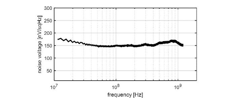
Fig. 17 Measured noise voltage from the output buffer 
Fig. 18 Pulse shape of the laser pulse 
Fig. 1 Block diagram of a TOF based laser radar 
Fig. 7 Simplified noise model of the TIA 
Fig. 14 A photograph of the receiver chip 
Fig. 15 Measurement setup 
Fig. 2 Walk error 
TABLE 1 
Fig. 11 Schematic of the comparator 
Fig. 10 Schematic of the offset compensation together with the threshold adjustment structure 
Fig. 9 Schematic of the post-amplifier 
Fig. 4 Noise level vs. pulse width 
Fig. 3 TIA definition 
Fig. 21 Jitter of the leading edge of the pulse as a function of input amplitude 
Fig. 20Walk error as a function of input amplitude 
Fig. 12 Schematic of the level shifter 
Fig. 13 Output buffer 
Fig. 5 Block diagram of the receiver


