scispace - formally typeset
Search or ask a question
Journal ArticleDOI

A behaviour-based control architecture for heterogeneous modular, multi-configurable, chained micro-robots

TL;DR: A new control architecture designed for heterogeneous modular, multi-configurable, chained micro-robots is presented, which can automatically reconfigure its actions to adapt to unpredicted events (such as actuator failure).
About: This article is published in Robotics and Autonomous Systems.The article was published on 2012-12-01 and is currently open access. It has received 34 citations till now. The article focuses on the topics: Applications architecture & Reference architecture.

Summary (8 min read)

Jump to: [1. Introduction][2. Robot description][2.2. Rotation module][2.3. Inchworm modules][2.4. Helicoidal module][2.5. Other modules][3.1. Physical layout][3.2. Layer structure][3.3. Command exchange protocol][3.3.1. LLCs][3.3.2. HLC][3.4. Module description language (MDL)][3.4.1. Indicators][4. Low-control layer][4.1. Embedded behaviours][2. Perceptual behaviours: (attempt to gather information about the module and its environment): Self-diagnostic, Situation awareness, Environment diagnostic.][4.1.1. Avoid overheating][4.1.2. Avoid actuator damage][4.1.3. Avoid mechanical damages][4.1.4. Self-diagnostic][4.1.5. Situation awareness][4.1.6. Vertical and horizontal sinusoidal movements][4.1.8. Push-forward movement][4.2. Behaviour fusion][5. Heterogeneous middle layer][5.1. Communications][5.2. Configuration check][6. High-control layer][In the first case, the chain could perform an inchwormmovement, whereas this is not possible in the second one. There are three possible locations for the modules:][6.1. Behaviours][6.1.1. Balance/stability][6.1.2. Walking behaviours][6.1.3. Obstacle negotiation][6.1.4. Path following behaviours][6.1.5. Wandering][6.1.6. Goal oriented behaviours][6.2. Behaviour fusion][6.2.1. Action selection mechanism][7. Offline control][8.1. Validation][8.2. Simulation][8.3. Optimisation][8.4. Real experiments] and [9. Conclusions]

1. Introduction

  • The control architecture described in this article was designed for chained, modular micro-robots.
  • These micro-robots are composed of different types of drive module (heterogeneous modules) that can be arranged in different configurations, a feature called multi-configurability.
  • The closest robot to the state of the art relies on homogeneous modular robot architectures.
  • The MICROTUB architecture is mainly based on behaviours and is divided into three layers: a low-control layer that is embedded in the modules and makes decisions for the modules, a high-control layer that makes decisions that concern the entire robot, and a heterogeneous middle layer that acts as an interpreter between the central control and the modules.
  • Two features of the architecture are of special relevance: the module description language (MDL) and the offline control.

2. Robot description

  • MICROTUB is a semi-autonomous multi-configurable microrobot for small-diameter pipe inspection and maintenance.
  • It has been designed to explore pipes with a camera to detect breakages, holes, leaks and any type of defect [27].
  • The micro-robot is heterogeneous and modular, meaning that it is composed of different types of active (they are able to move) and passive (they have to be acted on) modules.
  • This interface allows for the mechanical and electrical connection between modules.
  • The electrical bus is composed of eight wires: Power (5v) and ground.

2.2. Rotation module

  • The rotation module is a two-degrees-of-freedom (DOF) module that allows rotations in the horizontal and vertical planes.
  • A combination of these modules can perform undulatory movement (snake-like) that makes the robot move forwards.

2.3. Inchworm modules

  • Two modules have been developed to perform inchworm (or worm-like) movements: an extension module and a support module.
  • The inchworm mode of locomotion allows the robot to manoeuvre in small spaces.
  • The support module is used to fix the microrobot to the pipe; thus, this module does not move.

2.4. Helicoidal module

  • The helicoidal module was designed to be a fast-drive module able to push othermodules.
  • When the head turns, it goes forwards in a helicoidalmovement (helped by the distribution of thewheels that form a 15° anglewith the vertical) that pulls the body of the micro-robot forwards.
  • The wheels of the body help to keep themodule centred in the pipe and prevent the body from turning.

2.5. Other modules

  • Some othermodules that have been designed (but not built) are the traveller module, the sensor module and the battery module.
  • The traveller module is used to compute the travelled distance by using several wheels featuring encoders and an appropriate algorithm.
  • It has been specially designed for pipes.
  • The sensor module is a passive module that includes different types of sensor, such as temperature and humidity sensors.
  • Currently, the micro-robot requires a cable connection for both the power supply and video transmission.

3.1. Physical layout

  • The hardware architecture is shown in Fig. 3; the modules hold an embedded control board, and they are connected via the I2C bus.
  • Modules are also connected to their neighbours through a wire (synchronism line).

3.2. Layer structure

  • For the proposed architecture, a semi-distributed control has been chosen.
  • It collects information from the modules, processes it, and sends information about the situation and state of the robot, as well as commands with objectives, to the modules.
  • It includes the following layers: – Heterogeneous Layer: agent that translates com- mands coming from the CC into specific module commands.
  • It translates the command ‘‘extend’’ into servomotor movements.
  • Mataric [29] defines behaviours as processes or control laws that achieve and/or maintain goals.

3.3. Command exchange protocol

  • The command exchange protocol is used for communication between modules and the CC.
  • I2C messages are structures composed of three fields: address, instruction and parameters (depending on the instruction, an I2C message may have none, one or several parameters).
  • Parameters are codified in the following manner: the first byte codes for the parameter (it is also used to determine the length of the bytes that follow), and the following bytes code for information.
  • Finally, instructions can be divided as follows (see Fig. 6): Low-level commands (LLCs): messages sent from the CC to the modules.
  • Messages sent from the operator to the central control, also known as High-level commands (HLCs).

3.3.1. LLCs

  • LLCs are commands sent by the CC to the modules and the answers to these messages.
  • Currently implemented LLC1 and LLC2 commands are shown in Tables 4 and 5 (at the end of the article), respectively.
  • The parameters of SIM (Send Info of the Module), AIM (Answer Info of the Module), SIE (Send information of the Environment) and AIE (Answer information of the Environment) commands (in Table 5) are shown in Table 7 (also at the end of the article).

3.3.2. HLC

  • The commands are specified in Table 6 (at the end of the article).
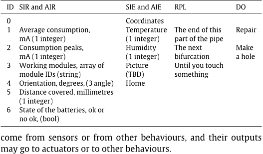
  • RPL parameters are composed of a first value, which indicates the type of position (Table 8 third column), plus the coordinates [(x, y, z)] in millimetres (three integers) (when needed).
  • The DO, SIR, AIR, SIE and AIE parameters are shown in Table 8.

3.4. Module description language (MDL)

  • MDL is essential for inferring functions or skills for the entire robot from the module features through rules and inference engines.
  • With MDL, it is possible to create units (groups of modules) that are able to perform more complex tasks.
  • It is based on a series of indicators that describe the tasks that the module can perform and a range of values that indicate the level of performance for each indicator.
  • Thus, MDL indicators canmalfunction or even stopworking in themodule.
  • The servomotor of a module may become stuck and may be able to turn only a percentage of its nominal range of motion.

3.4.1. Indicators

  • Push in pipe indicates that the module can go forwards by itself inside a pipe, whereas Push in open air refers to large spaces (including large-diameter pipes).
  • Rotate in its x/y/z axis means it has a DOF along that axis.
  • Attach and Detach to/from other modules is designed for selfreconfigurablemoduleswith active links (SMAs or electromechanical latches) [31,32].
  • Sense proximity front/backwards/lateral refers to any sensor that may detect obstacles.
  • Power supply indicates that it has a power supply to share.

4. Low-control layer

  • This section is dedicated to the behaviour-based control programs running in each of the modules, also called the low-level control.
  • The activation conditions are the only conditions that must be met for a behaviour to run.
  • Actions are the outputs of behaviours and define what the behaviours intend to do, including modifying the position and orientation of the module, blocking the motors, retrieving module state or actuator position.
  • The environment could be inside a pipe, open air7 or general terrain.
  • The working mode is information that is essential for every behaviour of the module to perform its tasks.

4.1. Embedded behaviours

  • There are several types of behaviour, which have been classified into several categories (as described in [18]) according to the type and complexity of the tasks they perform.
  • Some behaviours perform simple tasks, whereas some are based on other behaviours to perform more complex tasks.
  • The behaviours that have been defined are as follows:.

2. Perceptual behaviours: (attempt to gather information about the module and its environment): Self-diagnostic, Situation awareness, Environment diagnostic.

  • Walking behaviours (move the module): Vertical sinusoidal movement, Horizontal sinusoidalmovement,Worm-likemovement, Push-Forward movement.
  • Not all behaviours can act at the same time; thus, they have to be coordinated.
  • A description of the implemented behaviours is given next, followed by the coordination mechanisms.

4.1.1. Avoid overheating

  • The purpose of this behaviour is to make sure that the accumulated heat is maintained under certain limits to prevent circuit damage.
  • The heat produced in the coil of the motors by the electric current may lead to the burning of the coil.
  • (2) In the Laplace domain, Eq. (2) is expressed as Eq. (3). (6) The temperature of the environment is measured by a temperature sensor; the electrical current is obtained from the measurements of the sensors and the electrical and thermal resistance; and thermal capacitance is considered to be constant.
  • Fig. 9 shows the evolution of one of the servomotors of the rotation module under different situations.
  • When the servomotor releases, the temperature starts to decrease (from D to E), and when the servomotor is commanded to perform the movement again, the temperature again increases (from E in advance).

4.1.2. Avoid actuator damage

  • The purpose of this behaviour is to ensure that the torque of the motors remains under certain limits to avoid damage to themotors or actuators.
  • If the torque exceeds a certain limit, the servomotors are immediately released.
  • This purpose is achieved by keeping the instant current intensity under a certain limit, which has been determined experimentally.
  • The consumption increases very fast, and consequently it should be blocked below 120 mA.

4.1.3. Avoid mechanical damages

  • This behaviour is in charge of the mechanical security of the module, resolving any possible danger it may encounter owing to improper use of the actuators.
  • Singular points are produced, for example, when the links of each arm are aligned.
  • They are produced at angles of 25° (inside the workspace) and 147° (limit of the workspace).
  • The higher value can only be avoided by using software (see Fig. 11(b)).
  • Additionally, as described for the extension module, the mechanical design prevents that position from being reached, but that position should also be avoided.

4.1.4. Self-diagnostic

  • The purpose of this behaviour is to examine the functioning of themodule:whether the actuators canmove,whether the levels of intensity and torque are acceptable, whether the communication bus is working, whether the synchronism line is functioning, or whether the sensors are working correctly.
  • This behaviour records the setpoints (desired positions) of the actuators and compares them with their real positions.
  • If the positions are not approaching (and there is no problem with the torque and intensity, meaning it is not blocked), then there may be a problem with the actuator, and an alarm state is activated and communicated to the CC.
  • To verify the synchronism lines, in the configuration check phase, the behaviour checks if the signals Sin and Sout have been activated at any time.

4.1.5. Situation awareness

  • This behaviour attempts to determine the position of the module/micro-robot: inside a narrow pipe, a wide pipe, or open air.
  • It makes use of the contact sensors, infrared (IR) sensors, and the intensity and torque control system of the servomotors, among other sensors.
  • The touch (and camera) module plays a very important role because it features touch sensors to detect obstacles, which, in this case, are elbows and bifurcations.
  • Through the contact sensor, the module can detect whether it has collided into something, and other behaviours may act accordingly.

4.1.6. Vertical and horizontal sinusoidal movements

  • Modules with rotational DOFs can perform several movements (some of them are similar to snake-like rolling, rotating, or lateral shifting) based on a central pattern generator [33].
  • The position of the actuators follows two sinusoidal waves: one for the vertical actuators and one for the horizontal actuators (Eqs. (7) and (8)).
  • Inside pipes, it is also possible to negotiate elbows by pushing against the pipe walls.

4.1.8. Push-forward movement

  • This behaviour can be found in modules that have selfpropulsion capabilities, such as the helicoidal module.
  • This behaviour activates the actuator to move forwards or backwards as commanded.

4.2. Behaviour fusion

  • Some behaviours collaborate to achieve their goal , whereas others compete or act independently from each other.
  • Behaviours are divided into sets of priorities and tasks.
  • Its output can be overridden by LLC1 commands received directly from the CC.
  • Perceptual behaviours act independently because they only inform and have no actuator control.
  • Their output feeds back to the other behaviours with information regarding broken actuators, current situation, and other parameters.

5. Heterogeneous middle layer

  • The heterogeneous layer controls several tasks that take place between the module and the CC and/or other modules, such as communication.
  • Each time a command is receivedby themodule, it is processedby theheterogeneous layer and translated into specific instructions for themodule.
  • When an action has to be executed (i.e., extend), the CC sends an I2C message to every module with the command to follow.
  • The heterogeneous layer of each module translates this message into proper commands for the module.
  • The heterogeneous layer also controls the following tasks: communications, configuration check and MDL phase.

5.1. Communications

  • The heterogeneous layer receives commands from the CC and sends commands to the CC when the CC asks if there is something to communicate .
  • This process is how the modules communicate with the CC or other modules.
  • In the inverse procedure, the module sends a command to the CC, and if necessary, the heterogeneous layer translates the message.

5.2. Configuration check

  • The purpose of this task is to determine the configuration of the micro-robot and the position of the modules in the robots chain.
  • The first time this behaviour acts is after the mechanical connection of the modules and power-up, when the phase of awareness starts: every module knows its position in the modular chain.
  • This procedure occurs as follows (see Fig. 14): The CC sends a GPS message to all modules.
  • All modules activate their synchronism lines. .
  • The second module sends a PC1 message and puts its Sin synchronism line down, and thus, the first module knows it has finished.

6. High-control layer

  • The CC represents the high-control layer in the control architecture.
  • It is also based on behaviours that target the entire micro-robot.
  • To determine the capabilities of the robot, the CC makes use of an inference engine and a set of rules that make use of the MDL commands from each module to set the capabilities for the entire micro-robot.
  • Modules can be grouped into units to develop different capabilities; these units can in turn be grouped into super-units to possess even newer capabilities.
  • The capabilities of the entire micro-robot are the consequence of a combination of the capabilities of all modules and the position of the modules in the chain.

In the first case, the chain could perform an inchwormmovement, whereas this is not possible in the second one. There are three possible locations for the modules:

  • They can develop their capabilities independently of where are they placed, also known as Anywhere.
  • Anywhere Sequential Adjacent Robot Bat Rot +.
  • Then, capabilities are inserted in the rules, and those that are fulfilled are activated.
  • The CC can also deduce or infer which modules are needed for a specific task.

6.1. Behaviours

  • Continuing with the classification made in Section 4.1, the behaviours that have been defined for the CC are shown in the following list.
  • As explained previously, some behaviours perform simpler tasks, whereas more complex behaviours are based on these to perform more complex tasks.
  • Balance/stability, also known as 1. Postural behaviours.
  • Edge following, Pipe following, Stripe following, also known as 4. Path following behaviours.

6.1.1. Balance/stability

  • This behaviour is responsible for determining the orientation of the robot and changing it when necessary in order to be in the correct position for the current task.
  • If neither of them is in the right position, the behaviour will make the necessary movements to place the module in the right position.
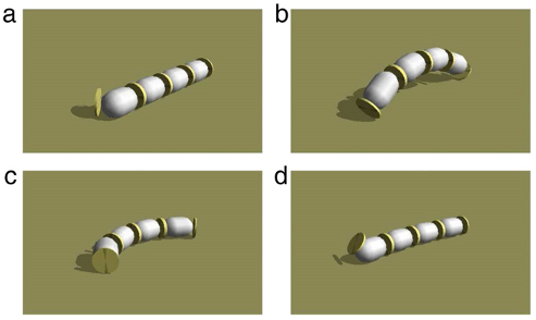
  • In the vertical sinusoidal wave movement, if the robot lays down, it is necessary to recover the position before continuing with the vertical sinusoidal movement.
  • In (b), the robot makes an arc and consequently falls down as shown in (c).
  • Then, it orients itself into a straight position, leaving the first degree of freedom vertical.

6.1.2. Walking behaviours

  • The move straight forward/backward behaviour controls the forward and backward movements of the micro-robot.
  • The use of one or another depends on the type of modules comprising the robot, the predominant modules, the environment through which it is moving and the state of the module (e.g., in terms of power supply andmechanical viability).
  • If the predominant modules are rotation modules, a snakelike gait is performed.
  • They only have to relay the signals coming from the synchronism line.
  • As mentioned previously, there are several types of movement that a micro-robot can perform, such as lateral shifts and rolling gaits.

6.1.3. Obstacle negotiation

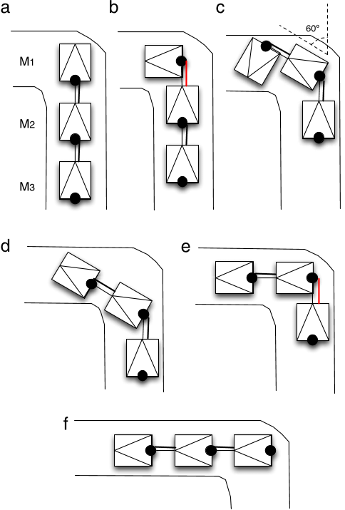
  • When something is detected in the path of the micro-robot, the behaviour is in charge of selecting the appropriate actions to move around the obstacle.
  • The robotmust then select the actions to negotiate the turn.
  • When an obstacle is encountered in the open air, it is slightly more complicated because there are many available options.
  • The easiest way is to go back and then slightly turn and go forwards.
  • If the object is detected again, the same algorithm is performed.

6.1.4. Path following behaviours

  • Edge followingmakes use of distance (IR) and touch sensors and seeks to keep the micro-robot from operating too close to a wall or object.
  • Depending on the measurements received from the IR sensors of the modules, the behaviour will output the coordinates where the robot should go.
  • Pipe following controls themovement of the robot inside a pipe, trying to keep the best movement gait and negotiating elbows and bifurcations.

6.1.5. Wandering

  • This behaviour controls the movement of the robot when there is no specific task selected.
  • The robot moves around, looking for possible damage and trying to avoid colliding into an obstacle.
  • It also may follow the pipes by making a map of the path using the travelled distance measuring system.

6.1.6. Goal oriented behaviours

  • The behaviours reach a place and reach a landmark function in a similar manner.
  • Starting from its own position, the behaviour estimates where the objective is and moves the robot in that direction.
  • The behaviour ’find a pipe break’ utilises the wandering behaviour tomove inside the pipewhile looking for breaks or holes with the camera and IR sensors.
  • The repair behaviour is an example of what will be possible when repairing tools are developed and added to the robot.
  • The behaviour will control moving the robot while it repairs the damaged pipe.

6.2. Behaviour fusion

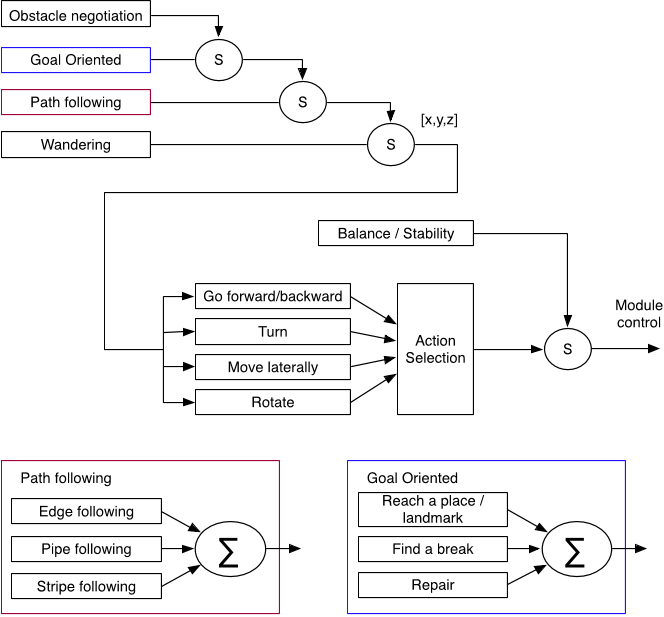
  • The behaviour fusion scheme for the CC algorithms is shown in Fig. 17.
  • Higher-level behaviours (i.e., path following, obstacle negotiation, exploration (wandering) and goal oriented) follow a subsumption-like procedure in order to coordinate.
  • Thus, obstacle negotiation is the highest-level behaviour.
  • This output is received by the walking behaviours, which compete amongst themselves for the control of themodules.
  • The output of the action selection mechanism can be suppressed by the balance/stability behaviour, which is in charge of keeping the micro-robot in the most appropriate position.

6.2.1. Action selection mechanism

  • The outputs of the four walking behaviours (go forwards, turn, move laterally and rotate) have to bemerged into a unique output.
  • Because these are all competing behaviours, one behaviour must be selected to follow.
  • The selection criteria depend on two factors: the situation and the destination of the micro-robot.
  • These also encode distance scales, such as near or far.

7. Offline control

  • Offline control refers to the control algorithms that occur when the micro-robot is not running (as opposed to online control, which has been covered in the previous sections).
  • These offline algorithms aim to select the best configuration of the micro-robot (regarding both module position and parameter configuration) for later use in the online control.
  • A physically accurate robotic simulation system has been developed to provide a very efficient method of prototyping and verifying control algorithms, hardware design, and exploration systemdeployment scenarios.
  • Two types of GA have been developed: configuration demand: in heterogeneous configurations, for a given task, the GA has to determine which modules to use for an optimal configuration and/or the optimal position of the modules in the chain.
  • The results of these offline algorithms feed the action selection mechanisms and the inference engine rules of the CC, helping to develop new rules.

8.1. Validation

  • Validation experiments have been performed regarding not only external parameters (position, velocity) but also internal variables (torque, intensity).
  • The simulator has been validatedwith data taken from real modules to adjust its parameters as much as possible, to be able to generate newmovement patterns and gaits, and to test new module concepts.
  • Table 10 shows some tests performed in the helicoidal module at different slopes.

8.2. Simulation

  • Several examples of the use of the architecture are provided.
  • Each of them is well suited for each respective situation in pipes or open air.
  • After interconnecting the modules, the system is aware of the configuration of the robot.
  • The combination of several rotationmodules plus an inchworm unit leads to several possible movements.

8.3. Optimisation

  • A micro-robot composed of six rotation modules performed a snake-like gait.
  • The algorithm goal was to optimise its sinusoidal wave parameter to move as fast as possible.
  • The chromosome was composed of 21 bits: seven each for the amplitude, angular velocity, and phase.
  • The results of the algorithm (for which the parameters can be seen in Table 11) are shown in Fig. 23.

8.4. Real experiments

  • In this section two experiments made with the real robot are presented.
  • In the second experiment (Fig. 25), a snake-like configuration is presented.

9. Conclusions

  • A control architecture for chained, modular robots composed of heterogeneous modules has been presented.
  • The control architecture is structured in three levels.
  • C. Unsal, P.K. Khosla, Mechatronic design of a modular self-reconfigurable robotics system, in: Proceeding of the 2000 IEEE International Conference on Intelligent Robots and Systems, pp. 1742–1747. [11].

Did you find this useful? Give us your feedback

Citations
More filters
Journal ArticleDOI
09 Jan 2020
TL;DR: The goal of the review is finding common approaches used in various areas of robotics to build on their basis a uniform methodology for designing scalable intelligent control systems for robots with a given level of fault tolerance on a unified component base.
Abstract: A review of robotic systems is presented. The paper analyzes applied hardware and software solutions and summarizes the most common block diagrams of control systems. The analysis of approaches to control systems scaling, the use of intelligent control, achieving fault tolerance, reducing the weight and size of control system elements belonging to various classes of robotic systems is carried out. The goal of the review is finding common approaches used in various areas of robotics to build on their basis a uniform methodology for designing scalable intelligent control systems for robots with a given level of fault tolerance on a unified component base. This part is dedicated to industrial robotics. The following conclusions are made: scaling in industrial robotics is achieved through the use of the modular control systems and unification of main components; multiple industrial robot interaction is organized using centralized global planning or the use of previously simulated control programs, eliminating possible collisions in working area; intellectual technologies in industrial robotics are used primarily at the strategic level of the control system which is usually non-real time, and in some cases even implemented as a remote cloud service; from the point of view of ensuring fault tolerance, the industrial robots developers are primarily focused on the early prediction of faults and the planned decommissioning of the robots, and are not on highly-avaliability in case of failures; industrial robotics does not impose serious requirements on the dimensions and weight of the control devices.

7 citations

Book ChapterDOI
Bo Xing1
01 Jan 2016
TL;DR: This chapter investigates the effect of artificial neural network (ANN) based control techniques for AAL robots, and provides an overview of applying emerging metaheuristic approaches to various smart robot control scenarios which have a great influence on various AAL robot related activities.
Abstract: The main purpose of introducing ambient assistive living (AAL) robots is to assist the disabled and elderly people at home. In recent years, this field has evolved quickly because of the enormous increase in computing power and availability of the improved variety of sensors and actuators. However, design of AAL robots control system is a huge challenge, which require solving issues related to two classes: design of mechanical structure and development of an efficient control system. In this chapter, we focus on the latter topic, since even relatively low quality hardware can be used for solving sophisticated tasks if the software control it correctly. The chapter starts by giving a vision of what heterogeneous AAL robots is supposed to look like and how a human is to act, navigate and function in it. Particularly, we investigate the effect of artificial neural network (ANN) based control techniques for AAL robots. To enhance the accuracy and convergence rate of ANN, a new method of neural network training is explored, i.e., grey wolf optimization (GWO). Moreover, we provide an overview of applying emerging metaheuristic approaches to various smart robot control scenarios which, from the author’s viewpoint, have a great influence on various AAL robot related activities, such as location identification, manipulation, communication, vision, learning, and docking capabilities. The findings of this work can provide a good source for someone who is interested in the research field of AAL robot control. Finally, we concludes with a discussion of some of the challenges that exist in the AAL robot control.

6 citations

01 Jan 2015
TL;DR: A novel motion planning system that utilize several locomotion generators in order to realize basic motions of the robots — motion primitives is proposed and the proposed planner then constructs the plan using these primitives.
Abstract: The thesis deals with the motion planning problem. In this problem, the task is to find a path or trajectory between two places in a known environment. Motion planning is mostly studied in robotics, but its applications are far beyond robotics in areas like computational biology or surgery. A wide range of motion planning problems can be solved using the concept of configuration space. Due to high number of dimensions of the configuration space, that is equal to the number of degrees of freedom of the robot, it is not possible to discretize the space and search it using standard state-space searching methods. Sampling-based motion planner like Probabilistic Roadmaps of Rapidly Exploring Random Tree solves the planning problems by randomized sampling of the configuration space. A well know bottleneck of the methods is the narrow passage problem. In order to speed up motion planner and to increase reliability of the planners, we propose to utilize the knowledge of the workspace to help sample the configuration space. The knowledge is represented using a path, the guides the sampling in the configuration space from the start configuration to the goal configuration. The guided sampling is studied in three challenging scenarios. The basic principle of the guided sampling is introduced on the example of motion planning for mobile robots, which requires to sample the three-dimensional configuration space. The low dimensionality of the configuration space allows us to compute the guiding path as a geometric path in the workspace using standard path planning methods. A different approach to compute the guiding path is proposed solve the path planning problem for 3D objects, that requires to search the six-dimensional configuration space. The proposed method first solves a relaxed version of the problem by scaling down the geometry of the robot. The found solution is then iterative improved until the solution of the original problem is found. Finally, a novel motion planner is proposed for motion planning for modular robots. Modular robots are formed by connecting basic robotic modules. These robots can be reconfigured to various shapes and they represent systems with more than 6 degrees of freedom. Motion planning for modular robots is challenging also due to necessity to control many actuators in order to achieve a motion of the whole robot. We propose a novel motion planning system that utilize several locomotion generators in order to realize basic motions of the robots — motion primitives. The proposed planner then constructs the plan using these primitives.

6 citations


Cites background from "A behaviour-based control architect..."

  • ...Examples of heterogeneous systems are ModRed platform [21] and recent Symbrion/Replicator robots [156]....

    [...]

Journal ArticleDOI
TL;DR: This paper will review the existing control architectures to extract the main features of civil UAVs and provide a comparative study of the mentioned control approaches.
Abstract: Since civil Unmanned Aerial Vehicles (UAVs) are expected to perform a wide rang of mission, the subject of designing an efficient control architecture for autonomous UAV is a very challenging problem. Several contributions had been done in order to implement an autonomous UAV. The key challenge of all these contributions is to develop the global strategy. Robotic control approaches could be classified into six categories: Deliberative, Reactive, Hybrid, Behavior, Hybrid Behavior and subsumption approach. In this paper, we will review the existing control architectures to extract the main features of civil UAVs. The definition, advantage and drawback of each architecture will be highlighted to finally provide a comparative study of the mentioned control approaches.

5 citations


Cites background from "A behaviour-based control architect..."

  • ...Each of which is responsible for a particular task [36]....

    [...]

Proceedings ArticleDOI
01 Dec 2017
TL;DR: The results show that with optimal parameters of ak and ck gain of SPSA, the optimal result was proven achieved and the agent capable to reach its desired target successfully.
Abstract: This paper investigates the effect of Simultaneous Perturbation Stochastic Algorithm towards multi agent motion coordination performances. Parameters of a, A, a, c and y were applied based on the guidelines given and based on the optimal value found from investigation. Each parameter will be varied and the results will be observed to determine the optimal parameters for this case study. The results show that with optimal parameters of a k and c k gain of SPSA which are a=0.21, A=30, a=0.602, c=1, y=0.101 and with a quadratic loss function, the optimal result was proven achieved. The results of convergence time, percentage of agent movement and the number of iteration were recorded to verify that the agent capable to reach its desired target successfully. The reading shows that in average, the agent will reach its target in 14.53 sec with 138 number of iterations in a 5 times run.

3 citations

References
More filters
Book
01 May 1998
TL;DR: Following a discussion of the relevant biological and psychological models of behavior, the author covers the use of knowledge and learning in autonomous robots, behavior-based and hybrid robot architectures, modular perception, robot colonies, and future trends in robot intelligence.
Abstract: From the Publisher: foreword by Michael Arbib "Hard to put down and necessary to know -- Arkin's book provides a comprehensive intellectual history of robots and a thorough compilation of robotic organizational paradigms from reflexes through social interaction." -- Chris Brown, Professor of Computer Science, University of Rochester This introduction to the principles, design, and practice of intelligent behavior-based autonomous robotic systems is the first true survey of this robotics field. The author presents the tools and techniques central to the development of this class of systems in a clear and thorough manner. Following a discussion of the relevant biological and psychological models of behavior, he covers the use of knowledge and learning in autonomous robots, behavior-based and hybrid robot architectures, modular perception, robot colonies, and future trends in robot intelligence. The text throughout refers to actual implemented robots and includes many pictures and descriptions of hardware, making it clear that these are not abstract simulations, but real machines capable of perception, cognition, and action.

2,935 citations


"A behaviour-based control architect..." refers background in this paper

  • ...Simply put, a behaviour is a reaction to a stimulus [18]....

    [...]

  • ...Behaviour-based architectures are specifically appropriate for the design and control of semiautonomous artificial robots based on biological systems (because biological models often serve as the basis for the design of behaviour-based robotic systems [18]), for modular robots and for systems integrating both low- and high-level control [19]....

    [...]

  • ...There are several types of behaviour, which have been classified into several categories (as described in [18]) according to the type and complexity of the tasks they perform....

    [...]

Book
22 May 1998
TL;DR: Whence behaviour? animal behaviour robot behaviour behaviour based architectures representational issues for behavioural systems hybrid deliberative/rective architectures perceptual basis for behaviour-based control adaptive behaviour social behaviour fringe robotics - beyond behaviour.
Abstract: Whence behaviour? animal behaviour robot behaviour behaviour-based architectures representational issues for behavioural systems hybrid deliberative/rective architectures perceptual basis for behaviour-based control adaptive behaviour social behaviour fringe robotics - beyond behaviour.

2,431 citations

Journal ArticleDOI
TL;DR: Several of the key directions for the future of modular self-reconfigurable robotic systems, including the design, fabrication, motion planning, and control of autonomous kinematic machines with variable morphology are shown.
Abstract: The field of modular self-reconfigurable robotic systems addresses the design, fabrication, motion planning, and control of autonomous kinematic machines with variable morphology. Modular self-reconfigurable systems have the promise of making significant technological advances to the field of robotics in general. Their promise of high versatility, high value, and high robustness may lead to a radical change in automation. Currently, a number of researchers have been addressing many of the challenges. While some progress has been made, it is clear that many challenges still exist. By illustrating several of the outstanding issues as grand challenges that have been collaboratively written by a large number of researchers in this field, this article has shown several of the key directions for the future of this growing field

903 citations


"A behaviour-based control architect..." refers background in this paper

  • ...Among homogeneous modular robot architectures, three of them have been found to be of special interest: CONRO [13,5], PolyBot [14,15] and M-TRAN [16,17]....

    [...]

  • ...PolyBot presents the attribute/service model, which is specially designed for complex tasks that require communication between different modules....

    [...]

Proceedings ArticleDOI
Mark Yim1, David G. Duff1, Kimon Roufas1
24 Apr 2000
TL;DR: PolyBot is the first robot to demonstrate sequentially two topologically distinct locomotion modes by self-reconfiguration, and as the design evolves the issues of low cost and robustness will be resolved while exploring the potential of modular, self- reconfigurable robots.
Abstract: Modular, self-reconfigurable robots show the promise of great versatility, robustness and low cost. The paper presents examples and issues in realizing those promises. PolyBot is a modular, self-reconfigurable system that is being used to explore the hardware reality of a robot with a large number of interchangeable modules. PolyBot has demonstrated the versatility promise, by implementing locomotion over a variety of terrain and manipulation versatility with a variety of objects. PolyBot is the first robot to demonstrate sequentially two topologically distinct locomotion modes by self-reconfiguration. PolyBot has raised issues regarding software scalability and hardware dependency and as the design evolves the issues of low cost and robustness will be resolved while exploring the potential of modular, self-reconfigurable robots.

703 citations


"A behaviour-based control architect..." refers background in this paper

  • ...The use of electromechanical latches or magnets (as in [16,14]) for future modules so that they are able to attach and detach by themselves is being considered....

    [...]

  • ...Among homogeneous modular robot architectures, three of them have been found to be of special interest: CONRO [13,5], PolyBot [14,15] and M-TRAN [16,17]....

    [...]

  • ...PolyBot presents the attribute/service model, which is specially designed for complex tasks that require communication between different modules....

    [...]

Journal ArticleDOI
TL;DR: A novel action selection theory is presented which allows arbitration among goals and actions while producing fast and robust activity in a tight interaction loop with the environment.

565 citations


"A behaviour-based control architect..." refers background in this paper

  • ...Regarding behaviour-based architectures, apart from the wellknown Motor Schemas [20], Activation Networks [21] or DAMN [22], it is necessary to mention CAMPOUT [23,24], which is a very interesting architecture because it integrates different types of behaviour (e.g., primitive, composite, communication and coordination) and different arbitration mechanisms (e.g., prioritybased, state-based, voting and fuzzy)....

    [...]

  • ...Regarding behaviour-based architectures, apart from the wellknown Motor Schemas [20], Activation Networks [21] or DAMN [22], it is necessary to mention CAMPOUT [23,24], which is a very...

    [...]

Frequently Asked Questions (1)
Q1. What are the contributions mentioned in the paper "A behaviour-based control architecture for heterogeneous modular, multi-configurable, chained micro-robots" ?

In this paper, the authors present a control solution for chained, modular robots composed of different types of module ( heterogeneous modules ) that can be arranged in different configurations, a feature called multi-configurability.