scispace - formally typeset
Search or ask a question
Journal ArticleDOI

A behaviour-based control architecture for heterogeneous modular, multi-configurable, chained micro-robots

TL;DR: A new control architecture designed for heterogeneous modular, multi-configurable, chained micro-robots is presented, which can automatically reconfigure its actions to adapt to unpredicted events (such as actuator failure).
About: This article is published in Robotics and Autonomous Systems.The article was published on 2012-12-01 and is currently open access. It has received 34 citations till now. The article focuses on the topics: Applications architecture & Reference architecture.

Summary (8 min read)

Jump to: [1. Introduction][2. Robot description][2.2. Rotation module][2.3. Inchworm modules][2.4. Helicoidal module][2.5. Other modules][3.1. Physical layout][3.2. Layer structure][3.3. Command exchange protocol][3.3.1. LLCs][3.3.2. HLC][3.4. Module description language (MDL)][3.4.1. Indicators][4. Low-control layer][4.1. Embedded behaviours][2. Perceptual behaviours: (attempt to gather information about the module and its environment): Self-diagnostic, Situation awareness, Environment diagnostic.][4.1.1. Avoid overheating][4.1.2. Avoid actuator damage][4.1.3. Avoid mechanical damages][4.1.4. Self-diagnostic][4.1.5. Situation awareness][4.1.6. Vertical and horizontal sinusoidal movements][4.1.8. Push-forward movement][4.2. Behaviour fusion][5. Heterogeneous middle layer][5.1. Communications][5.2. Configuration check][6. High-control layer][In the first case, the chain could perform an inchwormmovement, whereas this is not possible in the second one. There are three possible locations for the modules:][6.1. Behaviours][6.1.1. Balance/stability][6.1.2. Walking behaviours][6.1.3. Obstacle negotiation][6.1.4. Path following behaviours][6.1.5. Wandering][6.1.6. Goal oriented behaviours][6.2. Behaviour fusion][6.2.1. Action selection mechanism][7. Offline control][8.1. Validation][8.2. Simulation][8.3. Optimisation][8.4. Real experiments] and [9. Conclusions]

1. Introduction

  • The control architecture described in this article was designed for chained, modular micro-robots.
  • These micro-robots are composed of different types of drive module (heterogeneous modules) that can be arranged in different configurations, a feature called multi-configurability.
  • The closest robot to the state of the art relies on homogeneous modular robot architectures.
  • The MICROTUB architecture is mainly based on behaviours and is divided into three layers: a low-control layer that is embedded in the modules and makes decisions for the modules, a high-control layer that makes decisions that concern the entire robot, and a heterogeneous middle layer that acts as an interpreter between the central control and the modules.
  • Two features of the architecture are of special relevance: the module description language (MDL) and the offline control.

2. Robot description

  • MICROTUB is a semi-autonomous multi-configurable microrobot for small-diameter pipe inspection and maintenance.
  • It has been designed to explore pipes with a camera to detect breakages, holes, leaks and any type of defect [27].
  • The micro-robot is heterogeneous and modular, meaning that it is composed of different types of active (they are able to move) and passive (they have to be acted on) modules.
  • This interface allows for the mechanical and electrical connection between modules.
  • The electrical bus is composed of eight wires: Power (5v) and ground.

2.2. Rotation module

  • The rotation module is a two-degrees-of-freedom (DOF) module that allows rotations in the horizontal and vertical planes.
  • A combination of these modules can perform undulatory movement (snake-like) that makes the robot move forwards.

2.3. Inchworm modules

  • Two modules have been developed to perform inchworm (or worm-like) movements: an extension module and a support module.
  • The inchworm mode of locomotion allows the robot to manoeuvre in small spaces.
  • The support module is used to fix the microrobot to the pipe; thus, this module does not move.

2.4. Helicoidal module

  • The helicoidal module was designed to be a fast-drive module able to push othermodules.
  • When the head turns, it goes forwards in a helicoidalmovement (helped by the distribution of thewheels that form a 15° anglewith the vertical) that pulls the body of the micro-robot forwards.
  • The wheels of the body help to keep themodule centred in the pipe and prevent the body from turning.

2.5. Other modules

  • Some othermodules that have been designed (but not built) are the traveller module, the sensor module and the battery module.
  • The traveller module is used to compute the travelled distance by using several wheels featuring encoders and an appropriate algorithm.
  • It has been specially designed for pipes.
  • The sensor module is a passive module that includes different types of sensor, such as temperature and humidity sensors.
  • Currently, the micro-robot requires a cable connection for both the power supply and video transmission.

3.1. Physical layout

  • The hardware architecture is shown in Fig. 3; the modules hold an embedded control board, and they are connected via the I2C bus.
  • Modules are also connected to their neighbours through a wire (synchronism line).

3.2. Layer structure

  • For the proposed architecture, a semi-distributed control has been chosen.
  • It collects information from the modules, processes it, and sends information about the situation and state of the robot, as well as commands with objectives, to the modules.
  • It includes the following layers: – Heterogeneous Layer: agent that translates com- mands coming from the CC into specific module commands.
  • It translates the command ‘‘extend’’ into servomotor movements.
  • Mataric [29] defines behaviours as processes or control laws that achieve and/or maintain goals.

3.3. Command exchange protocol

  • The command exchange protocol is used for communication between modules and the CC.
  • I2C messages are structures composed of three fields: address, instruction and parameters (depending on the instruction, an I2C message may have none, one or several parameters).
  • Parameters are codified in the following manner: the first byte codes for the parameter (it is also used to determine the length of the bytes that follow), and the following bytes code for information.
  • Finally, instructions can be divided as follows (see Fig. 6): Low-level commands (LLCs): messages sent from the CC to the modules.
  • Messages sent from the operator to the central control, also known as High-level commands (HLCs).

3.3.1. LLCs

  • LLCs are commands sent by the CC to the modules and the answers to these messages.
  • Currently implemented LLC1 and LLC2 commands are shown in Tables 4 and 5 (at the end of the article), respectively.
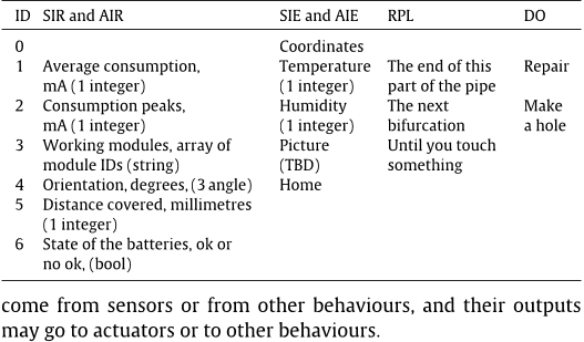
  • The parameters of SIM (Send Info of the Module), AIM (Answer Info of the Module), SIE (Send information of the Environment) and AIE (Answer information of the Environment) commands (in Table 5) are shown in Table 7 (also at the end of the article).

3.3.2. HLC

  • The commands are specified in Table 6 (at the end of the article).
  • RPL parameters are composed of a first value, which indicates the type of position (Table 8 third column), plus the coordinates [(x, y, z)] in millimetres (three integers) (when needed).
  • The DO, SIR, AIR, SIE and AIE parameters are shown in Table 8.

3.4. Module description language (MDL)

  • MDL is essential for inferring functions or skills for the entire robot from the module features through rules and inference engines.
  • With MDL, it is possible to create units (groups of modules) that are able to perform more complex tasks.
  • It is based on a series of indicators that describe the tasks that the module can perform and a range of values that indicate the level of performance for each indicator.
  • Thus, MDL indicators canmalfunction or even stopworking in themodule.
  • The servomotor of a module may become stuck and may be able to turn only a percentage of its nominal range of motion.

3.4.1. Indicators

  • Push in pipe indicates that the module can go forwards by itself inside a pipe, whereas Push in open air refers to large spaces (including large-diameter pipes).
  • Rotate in its x/y/z axis means it has a DOF along that axis.
  • Attach and Detach to/from other modules is designed for selfreconfigurablemoduleswith active links (SMAs or electromechanical latches) [31,32].
  • Sense proximity front/backwards/lateral refers to any sensor that may detect obstacles.
  • Power supply indicates that it has a power supply to share.

4. Low-control layer

  • This section is dedicated to the behaviour-based control programs running in each of the modules, also called the low-level control.
  • The activation conditions are the only conditions that must be met for a behaviour to run.
  • Actions are the outputs of behaviours and define what the behaviours intend to do, including modifying the position and orientation of the module, blocking the motors, retrieving module state or actuator position.
  • The environment could be inside a pipe, open air7 or general terrain.
  • The working mode is information that is essential for every behaviour of the module to perform its tasks.

4.1. Embedded behaviours

  • There are several types of behaviour, which have been classified into several categories (as described in [18]) according to the type and complexity of the tasks they perform.
  • Some behaviours perform simple tasks, whereas some are based on other behaviours to perform more complex tasks.
  • The behaviours that have been defined are as follows:.

2. Perceptual behaviours: (attempt to gather information about the module and its environment): Self-diagnostic, Situation awareness, Environment diagnostic.

  • Walking behaviours (move the module): Vertical sinusoidal movement, Horizontal sinusoidalmovement,Worm-likemovement, Push-Forward movement.
  • Not all behaviours can act at the same time; thus, they have to be coordinated.
  • A description of the implemented behaviours is given next, followed by the coordination mechanisms.

4.1.1. Avoid overheating

  • The purpose of this behaviour is to make sure that the accumulated heat is maintained under certain limits to prevent circuit damage.
  • The heat produced in the coil of the motors by the electric current may lead to the burning of the coil.
  • (2) In the Laplace domain, Eq. (2) is expressed as Eq. (3). (6) The temperature of the environment is measured by a temperature sensor; the electrical current is obtained from the measurements of the sensors and the electrical and thermal resistance; and thermal capacitance is considered to be constant.
  • Fig. 9 shows the evolution of one of the servomotors of the rotation module under different situations.
  • When the servomotor releases, the temperature starts to decrease (from D to E), and when the servomotor is commanded to perform the movement again, the temperature again increases (from E in advance).

4.1.2. Avoid actuator damage

  • The purpose of this behaviour is to ensure that the torque of the motors remains under certain limits to avoid damage to themotors or actuators.
  • If the torque exceeds a certain limit, the servomotors are immediately released.
  • This purpose is achieved by keeping the instant current intensity under a certain limit, which has been determined experimentally.
  • The consumption increases very fast, and consequently it should be blocked below 120 mA.

4.1.3. Avoid mechanical damages

  • This behaviour is in charge of the mechanical security of the module, resolving any possible danger it may encounter owing to improper use of the actuators.
  • Singular points are produced, for example, when the links of each arm are aligned.
  • They are produced at angles of 25° (inside the workspace) and 147° (limit of the workspace).
  • The higher value can only be avoided by using software (see Fig. 11(b)).
  • Additionally, as described for the extension module, the mechanical design prevents that position from being reached, but that position should also be avoided.

4.1.4. Self-diagnostic

  • The purpose of this behaviour is to examine the functioning of themodule:whether the actuators canmove,whether the levels of intensity and torque are acceptable, whether the communication bus is working, whether the synchronism line is functioning, or whether the sensors are working correctly.
  • This behaviour records the setpoints (desired positions) of the actuators and compares them with their real positions.
  • If the positions are not approaching (and there is no problem with the torque and intensity, meaning it is not blocked), then there may be a problem with the actuator, and an alarm state is activated and communicated to the CC.
  • To verify the synchronism lines, in the configuration check phase, the behaviour checks if the signals Sin and Sout have been activated at any time.

4.1.5. Situation awareness

  • This behaviour attempts to determine the position of the module/micro-robot: inside a narrow pipe, a wide pipe, or open air.
  • It makes use of the contact sensors, infrared (IR) sensors, and the intensity and torque control system of the servomotors, among other sensors.
  • The touch (and camera) module plays a very important role because it features touch sensors to detect obstacles, which, in this case, are elbows and bifurcations.
  • Through the contact sensor, the module can detect whether it has collided into something, and other behaviours may act accordingly.

4.1.6. Vertical and horizontal sinusoidal movements

  • Modules with rotational DOFs can perform several movements (some of them are similar to snake-like rolling, rotating, or lateral shifting) based on a central pattern generator [33].
  • The position of the actuators follows two sinusoidal waves: one for the vertical actuators and one for the horizontal actuators (Eqs. (7) and (8)).
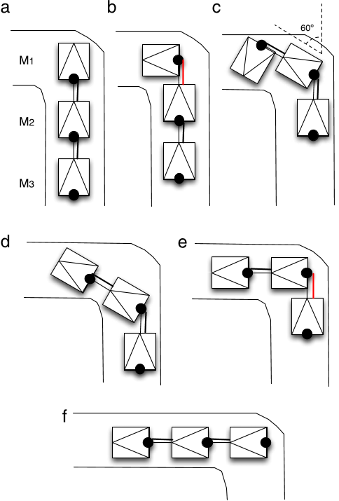
  • Inside pipes, it is also possible to negotiate elbows by pushing against the pipe walls.

4.1.8. Push-forward movement

  • This behaviour can be found in modules that have selfpropulsion capabilities, such as the helicoidal module.
  • This behaviour activates the actuator to move forwards or backwards as commanded.

4.2. Behaviour fusion

  • Some behaviours collaborate to achieve their goal , whereas others compete or act independently from each other.
  • Behaviours are divided into sets of priorities and tasks.
  • Its output can be overridden by LLC1 commands received directly from the CC.
  • Perceptual behaviours act independently because they only inform and have no actuator control.
  • Their output feeds back to the other behaviours with information regarding broken actuators, current situation, and other parameters.

5. Heterogeneous middle layer

  • The heterogeneous layer controls several tasks that take place between the module and the CC and/or other modules, such as communication.
  • Each time a command is receivedby themodule, it is processedby theheterogeneous layer and translated into specific instructions for themodule.
  • When an action has to be executed (i.e., extend), the CC sends an I2C message to every module with the command to follow.
  • The heterogeneous layer of each module translates this message into proper commands for the module.
  • The heterogeneous layer also controls the following tasks: communications, configuration check and MDL phase.

5.1. Communications

  • The heterogeneous layer receives commands from the CC and sends commands to the CC when the CC asks if there is something to communicate .
  • This process is how the modules communicate with the CC or other modules.
  • In the inverse procedure, the module sends a command to the CC, and if necessary, the heterogeneous layer translates the message.

5.2. Configuration check

  • The purpose of this task is to determine the configuration of the micro-robot and the position of the modules in the robots chain.
  • The first time this behaviour acts is after the mechanical connection of the modules and power-up, when the phase of awareness starts: every module knows its position in the modular chain.
  • This procedure occurs as follows (see Fig. 14): The CC sends a GPS message to all modules.
  • All modules activate their synchronism lines. .
  • The second module sends a PC1 message and puts its Sin synchronism line down, and thus, the first module knows it has finished.

6. High-control layer

  • The CC represents the high-control layer in the control architecture.
  • It is also based on behaviours that target the entire micro-robot.
  • To determine the capabilities of the robot, the CC makes use of an inference engine and a set of rules that make use of the MDL commands from each module to set the capabilities for the entire micro-robot.
  • Modules can be grouped into units to develop different capabilities; these units can in turn be grouped into super-units to possess even newer capabilities.
  • The capabilities of the entire micro-robot are the consequence of a combination of the capabilities of all modules and the position of the modules in the chain.

In the first case, the chain could perform an inchwormmovement, whereas this is not possible in the second one. There are three possible locations for the modules:

  • They can develop their capabilities independently of where are they placed, also known as Anywhere.
  • Anywhere Sequential Adjacent Robot Bat Rot +.
  • Then, capabilities are inserted in the rules, and those that are fulfilled are activated.
  • The CC can also deduce or infer which modules are needed for a specific task.

6.1. Behaviours

  • Continuing with the classification made in Section 4.1, the behaviours that have been defined for the CC are shown in the following list.
  • As explained previously, some behaviours perform simpler tasks, whereas more complex behaviours are based on these to perform more complex tasks.
  • Balance/stability, also known as 1. Postural behaviours.
  • Edge following, Pipe following, Stripe following, also known as 4. Path following behaviours.

6.1.1. Balance/stability

  • This behaviour is responsible for determining the orientation of the robot and changing it when necessary in order to be in the correct position for the current task.
  • If neither of them is in the right position, the behaviour will make the necessary movements to place the module in the right position.
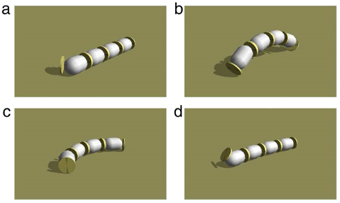
  • In the vertical sinusoidal wave movement, if the robot lays down, it is necessary to recover the position before continuing with the vertical sinusoidal movement.
  • In (b), the robot makes an arc and consequently falls down as shown in (c).
  • Then, it orients itself into a straight position, leaving the first degree of freedom vertical.

6.1.2. Walking behaviours

  • The move straight forward/backward behaviour controls the forward and backward movements of the micro-robot.
  • The use of one or another depends on the type of modules comprising the robot, the predominant modules, the environment through which it is moving and the state of the module (e.g., in terms of power supply andmechanical viability).
  • If the predominant modules are rotation modules, a snakelike gait is performed.
  • They only have to relay the signals coming from the synchronism line.
  • As mentioned previously, there are several types of movement that a micro-robot can perform, such as lateral shifts and rolling gaits.

6.1.3. Obstacle negotiation

  • When something is detected in the path of the micro-robot, the behaviour is in charge of selecting the appropriate actions to move around the obstacle.
  • The robotmust then select the actions to negotiate the turn.
  • When an obstacle is encountered in the open air, it is slightly more complicated because there are many available options.
  • The easiest way is to go back and then slightly turn and go forwards.
  • If the object is detected again, the same algorithm is performed.

6.1.4. Path following behaviours

  • Edge followingmakes use of distance (IR) and touch sensors and seeks to keep the micro-robot from operating too close to a wall or object.
  • Depending on the measurements received from the IR sensors of the modules, the behaviour will output the coordinates where the robot should go.
  • Pipe following controls themovement of the robot inside a pipe, trying to keep the best movement gait and negotiating elbows and bifurcations.

6.1.5. Wandering

  • This behaviour controls the movement of the robot when there is no specific task selected.
  • The robot moves around, looking for possible damage and trying to avoid colliding into an obstacle.
  • It also may follow the pipes by making a map of the path using the travelled distance measuring system.

6.1.6. Goal oriented behaviours

  • The behaviours reach a place and reach a landmark function in a similar manner.
  • Starting from its own position, the behaviour estimates where the objective is and moves the robot in that direction.
  • The behaviour ’find a pipe break’ utilises the wandering behaviour tomove inside the pipewhile looking for breaks or holes with the camera and IR sensors.
  • The repair behaviour is an example of what will be possible when repairing tools are developed and added to the robot.
  • The behaviour will control moving the robot while it repairs the damaged pipe.

6.2. Behaviour fusion

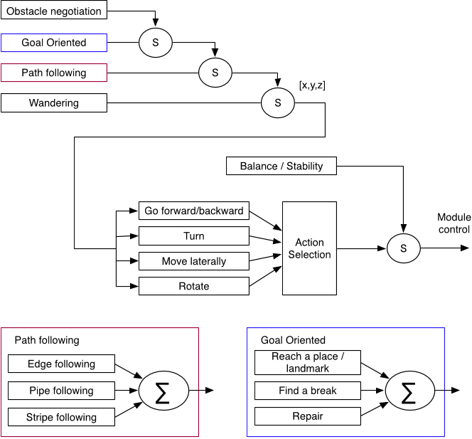
  • The behaviour fusion scheme for the CC algorithms is shown in Fig. 17.
  • Higher-level behaviours (i.e., path following, obstacle negotiation, exploration (wandering) and goal oriented) follow a subsumption-like procedure in order to coordinate.
  • Thus, obstacle negotiation is the highest-level behaviour.
  • This output is received by the walking behaviours, which compete amongst themselves for the control of themodules.
  • The output of the action selection mechanism can be suppressed by the balance/stability behaviour, which is in charge of keeping the micro-robot in the most appropriate position.

6.2.1. Action selection mechanism

  • The outputs of the four walking behaviours (go forwards, turn, move laterally and rotate) have to bemerged into a unique output.
  • Because these are all competing behaviours, one behaviour must be selected to follow.
  • The selection criteria depend on two factors: the situation and the destination of the micro-robot.
  • These also encode distance scales, such as near or far.

7. Offline control

  • Offline control refers to the control algorithms that occur when the micro-robot is not running (as opposed to online control, which has been covered in the previous sections).
  • These offline algorithms aim to select the best configuration of the micro-robot (regarding both module position and parameter configuration) for later use in the online control.
  • A physically accurate robotic simulation system has been developed to provide a very efficient method of prototyping and verifying control algorithms, hardware design, and exploration systemdeployment scenarios.
  • Two types of GA have been developed: configuration demand: in heterogeneous configurations, for a given task, the GA has to determine which modules to use for an optimal configuration and/or the optimal position of the modules in the chain.
  • The results of these offline algorithms feed the action selection mechanisms and the inference engine rules of the CC, helping to develop new rules.

8.1. Validation

  • Validation experiments have been performed regarding not only external parameters (position, velocity) but also internal variables (torque, intensity).
  • The simulator has been validatedwith data taken from real modules to adjust its parameters as much as possible, to be able to generate newmovement patterns and gaits, and to test new module concepts.
  • Table 10 shows some tests performed in the helicoidal module at different slopes.

8.2. Simulation

  • Several examples of the use of the architecture are provided.
  • Each of them is well suited for each respective situation in pipes or open air.
  • After interconnecting the modules, the system is aware of the configuration of the robot.
  • The combination of several rotationmodules plus an inchworm unit leads to several possible movements.

8.3. Optimisation

  • A micro-robot composed of six rotation modules performed a snake-like gait.
  • The algorithm goal was to optimise its sinusoidal wave parameter to move as fast as possible.
  • The chromosome was composed of 21 bits: seven each for the amplitude, angular velocity, and phase.
  • The results of the algorithm (for which the parameters can be seen in Table 11) are shown in Fig. 23.

8.4. Real experiments

  • In this section two experiments made with the real robot are presented.
  • In the second experiment (Fig. 25), a snake-like configuration is presented.

9. Conclusions

  • A control architecture for chained, modular robots composed of heterogeneous modules has been presented.
  • The control architecture is structured in three levels.
  • C. Unsal, P.K. Khosla, Mechatronic design of a modular self-reconfigurable robotics system, in: Proceeding of the 2000 IEEE International Conference on Intelligent Robots and Systems, pp. 1742–1747. [11].

Did you find this useful? Give us your feedback

Citations
More filters
Journal ArticleDOI
TL;DR: This paper investigates the leader-follower formation control problem for nonholonomic mobile robots based on a bioinspired neurodynamics based approach, and proposes an auxiliary angular velocity control law to guarantee the global asymptotic stability of the followers and to further guarantee the local asymPTotic Stability of the entire formation.

140 citations

Journal ArticleDOI
TL;DR: A transformation is given to convert the formation control problem for multiple nonholonomic mobile robots into a state consensus problem with rigorous proofs provided by using graph, matrix, and Lyapunov theories.
Abstract: In this paper, the distributed formation control problem for multiple nonholonomic mobile robots using consensus-based approach is considered. A transformation is given to convert the formation control problem for multiple nonholonomic mobile robots into a state consensus problem. Distributed control laws are developed for achieving the formation control objectives: a group of nonholonomic mobile robots at least exponentially converge to a desired geometric pattern with its centroid moving along the specified reference trajectory. Rigorous proofs are provided by using graph, matrix , and Lyapunov theories. Simulations are also given to verify the effectiveness of the theoretical results.

130 citations

Journal ArticleDOI
TL;DR: First, the formation control problem is converted into a state consensus problem by the aid of a variable transformation, and distributed kinematic controllers and adaptive dynamic controllers are developed for each robot such that a group of nonholonomic mobile robots asymptotically converge to a desired geometric pattern with its centroid moving along the specified reference trajectory.

91 citations

Journal ArticleDOI
TL;DR: This article presents a review on trends in modular reconfigurable robots, comparing the evolution of the features of the most significant robots over the years and focusing on the latest designs.
Abstract: This article presents a review on trends in modular reconfigurable robots, comparing the evolution of the features of the most significant robots over the years and focusing on the latest designs. These features are reconfiguration, docking, degrees of freedom, locomotion, control, communications, size, and powering. For each feature, some of the most relevant designs are presented and the current trends in the design are discussed.

79 citations

Book ChapterDOI
01 Jan 2016
TL;DR: This chapter is to explain behavior-based systems and their use in autonomous control problems and applications, and provides an overview of various robotics problems and application domains that have successfully been addressed or are currently being studied with behavior- based control.
Abstract: Nature is filled with examples of autonomous creatures capable of dealing with the diversity, unpredictability, and rapidly changing conditions of the real world. Such creatures must make decisions and take actions based on incomplete perception, time constraints, limited knowledge about the world, cognition, reasoning and physical capabilities, in uncontrolled conditions and with very limited cues about the intent of others. Consequently, one way of evaluating intelligence is based on the creature’s ability to make the most of what it has available to handle the complexities of the real world. The main objective of this chapter is to explain behavior-based systems and their use in autonomous control problems and applications. The chapter is organized as follows. Section 13.1 overviews robot control, introducing behavior-based systems in relation to other established approaches to robot control. Section 13.2 follows by outlining the basic principles of behavior-based systems that make them distinct from other types of robot control architectures. The concept of basis behaviors, the means of modularizing behavior-based systems, is presented in Sect. 13.3. Section 13.4 describes how behaviors are used as building blocks for creating representations for use by behavior-based systems, enabling the robot to reason about the world and about itself in that world. Section 13.5 presents several different classes of learning methods for behavior-based systems, validated on single-robot and multi-robot systems. Section 13.6 provides an overview of various robotics problems and application domains that have successfully been addressed or are currently being studied with behavior-based control. Finally, Sect. 13.7 concludes the chapter.

58 citations

References
More filters
Journal ArticleDOI
TL;DR: A novel robotic system called modular transformer (M-TRAN) is proposed, a distributed, self-reconfigurable system composed of homogeneous robotic modules that is able to metamorphose into robotic configurations such as a legged machine and generate coordinated walking motion without any human intervention.
Abstract: In this paper, a novel robotic system called modular transformer (M-TRAN) is proposed. M-TRAN is a distributed, self-reconfigurable system composed of homogeneous robotic modules. The system can change its configuration by changing each module's position and connection. Each module is equipped with an onboard microprocessor, actuators, intermodule communication/power transmission devices and intermodule connection mechanisms. The special design of M-TRAN module realizes both reliable and quick self-reconfiguration and versatile robotic motion. For instance, M-TRAN is able to metamorphose into robotic configurations such as a legged machine and hereby generate coordinated walking motion without any human intervention. An actual system with ten modules was built and basic operations of self-reconfiguration and motion generation were examined through experiments. A series of software programs has also been developed to drive M-TRAN hardware, including a simulator of M-TRAN kinematics, a user interface to design appropriate configurations and motion sequences for given tasks, and an automatic motion planner for a regular cluster of M-TRAN modules. These software programs are integrated into the M-TRAN system supervised by a host computer. Several demonstrations have proven its capability as a self-reconfigurable robot.

552 citations


"A behaviour-based control architect..." refers background in this paper

  • ...These new features include amiddle layer similar to that ofM-TRAN’s, butwith someheterogeneous capabilities that permit the triggering of similar actions in different modules (as opposed to CONRO’s hormones), a communications model that allows heterogeneous modules to communicate amongst themselves and to communicate its capabilities, and a set of behaviours to cover low- and high-control layers....

    [...]

  • ...The use of electromechanical latches or magnets (as in [16,14]) for future modules so that they are able to attach and detach by themselves is being considered....

    [...]

  • ...Among homogeneous modular robot architectures, three of them have been found to be of special interest: CONRO [13,5], PolyBot [14,15] and M-TRAN [16,17]....

    [...]

  • ...M-TRAN presents a distributed control and a three-layer architecture with a lowlevel middle layer for communication and high-level control (used for reconfigurations)....

    [...]

Journal ArticleDOI
TL;DR: An architecture is presented in which distributed task-achieving modules, or behaviours, cooperatively determine a mobile robot's path by voting for each of various possible actions, and an arbiter performs command fusion and selects that action which best satisfies the prioritized goals of the system.
Abstract: An architecture is presented in which distributed task-achieving modules, or behaviours, cooperatively determine a mobile robot's path by voting for each of various possible actions. An arbiter then performs command fusion and selects that action which best satisfies the prioritized goals of the system, as expressed by these votes, without the need to average commands. Command fusion allows multiple goals and constraints to be considered simultaneously. Examples of implemented systems are given, and future research directions in command fusion are discussed.

484 citations


"A behaviour-based control architect..." refers background in this paper

  • ...Regarding behaviour-based architectures, apart from the wellknown Motor Schemas [20], Activation Networks [21] or DAMN [22], it is necessary to mention CAMPOUT [23,24], which is a very interesting architecture because it integrates different types of behaviour (e.g., primitive, composite, communication and coordination) and different arbitration mechanisms (e.g., prioritybased, state-based, voting and fuzzy)....

    [...]

  • ...Regarding behaviour-based architectures, apart from the wellknown Motor Schemas [20], Activation Networks [21] or DAMN [22], it is necessary to mention CAMPOUT [23,24], which is a very...

    [...]

ReportDOI
01 Jan 1994
TL;DR: A novel formulation of reinforcement learning is proposed that makes behavior selection learnable in noisy, uncertain multi-agent environments with stochastic dynamics, and enables and accelerates learning in complex multi-robot domains.
Abstract: This thesis addresses situated, embodied agents interacting in complex domains. It focuses on two problems: (1) synthesis and analysis of intelligent group behavior, and (2) learning in complex group environments. Behaviors are proposed as the appropriate level for control and learning. Basic behaviors are introduced as building blocks for synthesizing and analyzing system behavior. The thesis describes the process of selecting such basic behaviors, formally specifying them, algorithmically implementing them, and empirically evaluating them. All of the proposed ideas are validated with a group of up to 20 mobile robots using a basic behavior set consisting of: avoidance, following, aggregation, dispersion, and homing. The set of basic behaviors acts as a substrate for achieving more complex high-level goals and tasks. Two behavior combination operators are introduced, and verified by combining subsets of the above basic behavior set to implement collective flocking and foraging. A methodology is introduced for automatically constructing higher-level behaviors by learning to select among the basic behavior set. A novel formulation of reinforcement learning is proposed that makes behavior selection learnable in noisy, uncertain multi-agent environments with stochastic dynamics. It consists of using conditions and behaviors for more robust control and minimized state-spaces, and a reinforcement shaping methodology that enables principled embedding of domain knowledge with two types of shaping functions: heterogeneous reward functions and progress estimators. The methodology outperforms two alternatives when tested on a collection of robots learning to forage. The proposed formulation enables and accelerates learning in complex multi-robot domains. The generality of the approach makes it compatible with the existing reinforcement learning algorithms, allowing it to accelerate learning in a variety of domains and applications. The presented methodologies and results are aimed at extending our understanding of synthesis, analysis, and learning of group behavior. (Copies available exclusively from MIT Libraries, Rm. 14-0551, Cambridge, MA 02139-4307. Ph. 617-253-5668; Fax 617-253-1690.)

425 citations


"A behaviour-based control architect..." refers background in this paper

  • ...Mataric [29] defines behaviours as processes or control laws that achieve and/or maintain goals....

    [...]

Proceedings ArticleDOI
01 Mar 1987
TL;DR: Motor schemas are proposed as a basic unit of behavior specification for the navigation of a mobile robot and a variant of the potential field method is used to produce the appropriate velocity and steering commands for the robot.
Abstract: Motor schemas are proposed as a basic unit of behavior specification for the navigation of a mobile robot. These are multiple concurrent processes which operate in conjunction with associated perceptual schemas and contribute independently to the overall concerted action of the vehicle. The motivation behind the use of schemas for this domain is drawn from neuroscientific, psychological and robotic sources. A variant of the potential field method is used to produce the appropriate velocity and steering commands for the robot. An implementation strategy based on available tools at UMASS is described. Simulation results show the feasibility of this approach.

418 citations


"A behaviour-based control architect..." refers background in this paper

  • ...Regarding behaviour-based architectures, apart from the wellknown Motor Schemas [20], Activation Networks [21] or DAMN [22], it is necessary to mention CAMPOUT [23,24], which is a very interesting architecture because it integrates different types of behaviour (e.g., primitive, composite, communication and coordination) and different arbitration mechanisms (e.g., prioritybased, state-based, voting and fuzzy)....

    [...]

  • ...Regarding behaviour-based architectures, apart from the wellknown Motor Schemas [20], Activation Networks [21] or DAMN [22], it is necessary to mention CAMPOUT [23,24], which is a very...

    [...]

Journal ArticleDOI
TL;DR: In this article, the authors show that many mobile robots used for ground operations are wheel-driven, but serpentine robots offer many advantages over the wheeled variety, and they outline what those advantages are.
Abstract: Many mobile robots used for ground operations are wheel driven, but serpentine robots offer many advantages over the wheeled variety. The article outlines what those advantages are.

369 citations

Frequently Asked Questions (1)
Q1. What are the contributions mentioned in the paper "A behaviour-based control architecture for heterogeneous modular, multi-configurable, chained micro-robots" ?

In this paper, the authors present a control solution for chained, modular robots composed of different types of module ( heterogeneous modules ) that can be arranged in different configurations, a feature called multi-configurability.