
All figures (10)
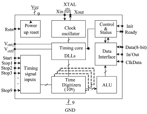
Fig. 5. The block diagram of the TDC. 
Fig. 1. Pulsed TOF laser rangefinder. 
Fig. 4. Simplified block diagram of the receiver IC. 
Fig. 3. Principle of timing walk compensation based on the measurements of pulse width and rise time. 
Fig. 2. Optical pulse shape (905D1S2J03Y with MOS pulse driver) of the transmitter recorded with a 25 GHz optical measuremnt head. 
Fig. 6. TDC measurement core based on counter and 2-level interpolation. 
Fig. 8. Transmitter and receiver optics. 
Fig. 7. Photograph of the measurement PCB including the receiver and TDC chips. 
Fig. 10. Single-shot distribution of 5,000 hits of walk-compensated results at 34 m measured for a) a black piece of cardboard (ρ~0.12) and b) a directional diamond grade reflective sheet (ρ >>1). 
Fig. 9. Pulsed TOF laser radar measurement track.


14 May 2018-