
All figures (9)
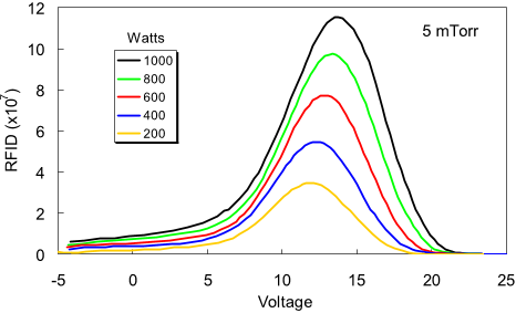
Fig. 4. RFIDs versus voltage on the collector plate relative to ground at 5 mTorr and various RF powers. 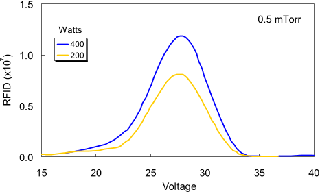
Fig. 5. RFIDs versus voltage relative to ground at 0.5 mTorr. 
Fig. 3. B-field in the region below the stagnation point (at three radial positions), and the location of the discharge tube when the antenna is at 60 G. 
Fig. 6. Schematic of the experimental chamber showing locations of three probe ports and the sliding mount for the RFIA sensor. 
Fig. 7. Location where a double-layer would occur in the absence of the RFIA sensor. The location is not a single point because B is not uniform in the discharge. 
Fig. 1. Argon helicon discharge with a permanent magnet. 
Fig. 2. Small squares: B-lines around a large annular magnet. Large squares: two possible positions of the discharge tube. The B-field can be varied by moving the magnet vertically relative to the discharge. 
Fig. 8. Downstream ion distributions at Port 2 versus RF power at 15 mTorr. Two curves at 700 W show reproducibility at beginning and end of run. 
Fig. 9. Ion distributions at Port 2 with at 1000 and 400 W with top plate voltages of 0 V (black curves), −24 V (red curves), and +24 V (blue curves).


