scispace - formally typeset
Search or ask a question
Proceedings ArticleDOI

A Comparison of Two Methods Used to Deal with Saturation of Multiple, Redundant Aircraft Control Effectors

Mark David Nelson1
05 Aug 2002-
TL;DR: In this article, the authors present a list of acknowledgements and acknowledgements for the work of the authors of this article. But they do not mention the authors' work in this paper.
Abstract: . . . . . . . . . . . . . . . . . . . . . . . . . . . . . . . . . . . . . . . . ii Acknowledgments . . . . . . . . . . . . . . . . . . . . . . . . . . . . . . . . . . . . iii Table of

Summary (6 min read)

List of Figures

  • Star represents the starting vertex of the AMS.
  • The method of control vector scaling is implemented.
  • The method of pitch prioritization is implemented.
  • 42 5.7 Desired moment time histories plotted with attained moments for the offset left approach using the method of scaling the moment direction.
  • . . . 46 5.10 Longitudinal and lateral stick time histories for the offset high left approach using both methods.

1.1 Background

  • Classically, aircraft flight controls have been designed to use a single control effector to produce a desired moment about a specific rotational degree of freedom.
  • These additional arise from freeing opposing moment generators and controlling them independently.
  • Left and right horizontal tails can be used individually to produce roll, pitch or yaw moments.
  • With this arrangement the number of control effectors on an aircraft could total close to 20.
  • Most of these solutions are not realistic for an actual aircraft due to control limits created by the physical geometry of the effector and aerodynamic constraints on the surfaces.

1.2 Allocation Problem

  • The distribution of controls to obtain a certain objective is the general allocation problem.
  • These equations come from Newton’s Second Law of Motion and are frequently linearized about some reference condition and written ẋ = Ax+Bu (1.1).
  • The problem is solved by finding a control vector to produce desired aircraft dynamics.
  • This research examines such a method in dealing with these unattainable moments.
  • Note that other difficulties arise in control allocation such as the fact that the linearized equation md =.

1.3 Allocation Methods

  • A schematic of the general arrangement of a control system, with control law and control allocator, is presented in Figure 1.1.
  • Dynamic inversion allows one to tailor the shape of the responses by calculating the forces and moments required of the controls.
  • Some of these methods of control allocation are presented in Bordignon [4].
  • Some methods such as daisy chaining and generalized inverses are often used [4].
  • All of these methods provide a simple linear approach to solving the allocation.

1.4 Attainable Moments

  • The term attainable refers to the set of moments that can be generated given the physical limits of the effectors.
  • Control vector solutions that are within the physical limits are admissible solutions.
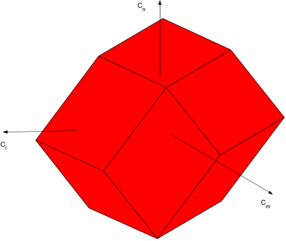
  • The calculation of the attainable moment subset (AMS) is simple and defines individual facets of the polytope [5].
  • One facet is defined by two controls free to vary, with all other controls being saturated.
  • An additional constraint to the control allocation problem could involve the rate limits for each effector.

1.5 Research Objectives

  • It was the purpose of this research to provide an insight into the problem of unattainable moments.
  • A method of pitch prioritization was investigated to allocate controls in the case of an unattainable moment and compared with the method of scaling the moment direction.
  • Pitch prioritization allocates controls while preserving the stability augmentation in the longitudinal axis of an unstable airframe.
  • An F-18-like airframe was used as a testbed to perform the research and evaluate the performance of prioritization.
  • Prioritization of a single objective during situations that ask for unattainable moments was.

2.1 Introduction

  • Before the days of redundant control effectors and complex control laws the control allocation problem was simply dealt with by the use of mechanical linkages between the pilot’s stick and pedals, and the control surfaces.
  • Control systems since then have increased in complexity such as using an aileron/rudder interconnect to offset the adverse yaw effect during a turn.
  • Even more complexity comes about when additional controls are developed and added to the airframe in an attempt to provide more maneuverability.
  • Redundancy in aircraft controls has significantly altered the complexity of the control allocation problem.
  • Several algorithms have been developed over the years to solve this problem.

2.2 Background

  • Less complex algorithms such as generalized inverses have been used successfully in the past.
  • The most popular of these control allocation algorithms is the Minimum Norm solution.
  • This solution arranges the controls to produce the desired objectives while minimizing control energy.
  • This method simply uses the pseudo-inverse solution to minimize the 2-norm of the control vector solution.
  • There are several well-known ways to derive the pseudo-inverse solution that may be found in any text dealing with the underdetermined systems of linear 9.

2.3 Cascading Generalized Inverses

  • One method called Cascading Generalized Inverse (CGI) was developed by Bordignon [4].
  • This method uses the idea that if a generalized inverse commands a solution in which one or more controls exceed a limit, so long as not all are saturated, the controls are set at the limits, and the rest of the controls are redistributed to achieve the desired objectives.
  • In other words, if a control is commanded past its limit, it is set at the limit, and the effects of the control at saturation are subtracted from the desired objectives.
  • The method is repeated every time a control position is exceeded.
  • If all controls become saturated, the moment is unattainable using this method.

2.5 Bisecting Edge Searching Algorithm

  • The method described above is more or less a brute force method of determining the intersection of md with the surface of the AMS.
  • The method involved looking at a single facet defined by a pair of controls and determining whether the desired moment direction pointed toward this facet.
  • There is no guarantee that the intersection would be found before the last facet was tested.
  • The potential of searching the entire AMS meant that the number of floating point operations and computation time could be very high with the addition of control effectors.
  • The reader is referred to Durham and Scalera [6, 7] for the theory behind the algorithm and a comparison of the performance with other allocators.

2.5.1 Two-Dimensional Problem

  • The two dimensional problem is introduced as part of the solution to the three dimensional problem.
  • That is, the three dimensional problem can be solved by systematically repeated solutions of the two dimensional projections of the three dimensional problem.
  • B will then consist of two rows, with each element describing the effect each control has on the objectives.
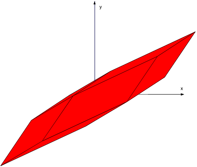
  • Figure 2.1 depicts an attainable moment subset, AMS, created from a four-control two-objective problem.
  • The vertex with the maximum x-component is identified on the AMS.

2.5.2 Three-Dimensional Problem

  • For the three-dimensional problem, consider md to consist of three objectives, causing the control effectiveness matrix to have three rows.
  • From this view point the problem resembles the two-dimensional problem and is solved in the same way.
  • There is an angle where the AMS can be rotated about the +x-axis such that the intersection of md, which is aligned with the +x-axis, with the AMS will lie exactly on a limb of the AMS as viewed from the +z-axis.
  • Small perturbations in this angle will identify two edges that define the facet that contains the intersection.
  • The rotation angle can not be calculated analytically, however, the angle is not needed, just.

3.2 F/A-18 Testbed

  • The testbed airframe used in this research was based off of an F/A-18A airframe simulation.
  • The greatest area in which the test-bed simulation differs from the original F/A-18A airframe is in the treatment of control effectors.
  • These effectors were retained to make the simulation compatible with existing F/A-18 aircraft simulations.
  • These controls are only used for initial trim and subsequent scheduling.
  • The F/A18 in PA mode schedules leading-edge flaps based on angle-of-attack.

3.3 Airframe Simulation

  • There are six files that were used in the simulation of the airframe: AERO.F, AEROPA.F, CONTROL.F, CONSTANTS.F, ENGINE.F, AND ALLOC.F.
  • This section explains the purpose of each routine.

3.3.1 Aero.f

  • AERO.F is an executive subroutine that calls subroutines based on the flight phase of the aircraft.
  • In this specific case AERO.F calls AEROPA.
  • The code then combines the aerodynamics from the non-linear scheduled/trimmed flight condition with the aerodynamics from the UGLOBAL array to produce the total aerodynamic forces and moments.

3.3.2 Aeropa.f

  • AEROPA.F is taken from the F/A-18 simulation and modified slightly to mesh with AERO.F and to include proper control scheduling.
  • This is the only code that gives the airframe F/A-18 like characteristics.

3.3.3 Control.f

  • Stick and rudder pedal commands are taken as inputs and converted into an angle-of-attack command αcmd, sideslip command βcmd, and a roll rate command pcmd.
  • These commands are input to a simple dynamic inversion control law that generates desired moments for the control allocation subroutine.

3.3.6 Alloc.f

  • This code is the BESA control allocator that produces required control deflections for desired moments.
  • The BESA method was explained in Chapter 2.

3.4 Simulation Environment

  • Naval Air Systems Command provided the original F/A-18 simulation code in FORTRAN that was implemented on a Silicon Graphics Origin 2000TM Deskside System with two CPU’s running at 180 MHz with 256 MB of RAM and a 4 GB disk.
  • CASTLE is a 6-degree-of-freedom non-linear aircraft simulation architecture developed by Naval Air Warfare Center’s Manned Flight Simulator branch (MFS) [11].
  • The visual scene is calligraphic depicting a dusk or night environment.
  • The visual database includes scenes for a carrier landing approach, and a naval air station.
  • The stick feel is produced using an electronic control loader and can be modified through software to produce a realistic feel of any actual aircraft stick.

3.5 Airframe Validity

  • The airframe in this research was modeled after the F-18A airframe for ease of implementation on other users computers that already had the original F-18 airframe.
  • The modifications that were made were simply added subroutines to transform the airframe as needed.

4.1 Introduction

  • The method of prioritization has rarely been used for problems such as unattainable moments that lead to inadmissible control solutions.
  • The use of pitch prioritization provides one method of dealing with unattainable moment commands.
  • As previously stated, pitch axis prioritization was chosen because of the popularity of relaxing the static margin of an aircraft to reduce trim drag.
  • To stabilize the airframe the control law requires a certain amount of pitching moment.
  • Prioritization the pitching-moment requirement will ensure that the maximum amount of pitch can be attained during any maneuver.

4.2 Sizing the Attainable Moment Subset

  • Control effectiveness was determined by the linearization of the F/A-18 aerodynamic database described in Chapter 3.
  • The controls that were added to the testbed airframe were given the 25.

4.3 Method of Pitch Prioritization and Moment Direc-

  • Tion Preservation Scaling the control solution vector preserves the moment direction while decreasing the magnitude.
  • Preserving the moment direction will simply decrease the magnitude of the moment vector, using the solution on the boundary of the AMS.
  • The light green arrow indicates the desired moment for a specific time during the maneuver.
  • Prioritizing the pitch axis, the control effectors are able to provide the full amount of desired pitching moment.

5.1 Background

  • Maneuvers that cause the control law to require unattainable moments and require the majority of the controls to be saturated are used to investigate the comparison between the two methods of dealing with unattainable moments.
  • An important aspect of the results in this research was how the airplane felt to the pilot in addition to the hard data that was plotted.
  • One evaluation pilot was used to fly all the data represented in this paper.
  • Several flights were flown by other pilots, however those results are not included here.
  • The test pilot has a background in Navy fighters, carrier suitability, and flight testing.

5.2 Offset Carrier Approach maneuver

  • Aerodynamic control effectiveness reduces with a decrease in the dynamic pressure.
  • As a result, an aircraft requires larger control deflections to produce the desired amount of force and moment.
  • An offset powered approach to an aircraft carrier was chosen for evaluation in this research since it provided the low dynamic pressure flight condition as well as large stick inputs and a high pilot workload.

5.2.1 Offset Carrier Approach maneuver: Description

  • For this maneuver the static margin of the airframe was relaxed so that the airframe was unstable in the longitudinal axis.
  • The control law kept the airframe stable during normal flight with small stick inputs.
  • Offset Left - Airframe was offset to the left of centerline eight degrees and required more lateral maneuvering than pitch to correct the offset.
  • The approach was offset eight degrees left of centerline and three degrees above the desired glide-slope.
  • The pilot began the maneuver at the same point.

5.2.2 Offset Left Carrier Approach maneuver: Results

  • The following data represents two different offset left approaches flown from the same initial conditions.
  • One approach implemented the method of scaling the moment direction while the other used the method of pitch prioritization.
  • Figure 5.2 plots the saturation of each method for an offset left maneuver.
  • The yellow hatching indicates when the controls are saturated.
  • The area of saturation for the lateral-directional requirement occured when the pitch requirement was near saturation indicating that most of the controls had been used for pitching moment.

5.2.3 Offset High Left Carrier Approach maneuver: Results

  • An additional offset approach was used to further evaluate the two methods of dealing with unattainable moments.
  • The prioritization mode was able to achieve all of the pitching moment without saturating any of the controls on the airframe.
  • The saturation plot for the scaling method ends early because the airframe diverged in pitch as soon as the corrective maneuver was applied.
  • These percentages are calculated as previously explained in section 5.2.2.
  • Figure 5.10 plots the stick movement throughout the entire flight using both methods.

5.2.4 Offset Carrier Approach maneuvers: Pilot Interpretation

  • The main trend seen in all the test flights was the pilot adaptation to how the aircraft handled.
  • This learning curve made it difficult to investigate all of the differences between the two different methods.
  • The one disconcerting tendency of the airframe while in pitch prioritization mode was the continuously changing amount of lateral control power during flight.
  • The method of scaling the desired moment direction gave the aircraft an unstable feel to the pilot during any kind of aggressive maneuver.
  • Overall, the airframe with pitch prioritization was “more smooth” compared to the flight with the method of scaling the moment direction implemented.

Summary and Conclusions

  • A comparison of two methods to deal with unattainable moments in an aircraft was performed using a testbed airframe that resembled an F/A-18 with a highly redundant control effector suite.
  • Control allocation utilizing the Bisecting, Edge Searching Algorithm was implemented on this airframe and a dynamic inversion control law was used to produce the desired aircraft handling qualities.
  • In extreme unstable cases prioritizing the pitch axis produced favorable characteristics with respect to the alternative of preserving the moment direction by scaling the control solution vector that the allocator produces.
  • Representative maneuvers that offered real-time evaluation of the two methods were flown with a pilot-in-the-loop.
  • The validity of these tasks were subject to pilot compensation, to the point where the pilot was required to remove any learning of how the aircraft feels from the desired task.

Did you find this useful? Give us your feedback

Figures (33)

Content maybe subject to copyright    Report

A Comparison of Two Methods Used to Deal with Saturation of
Multiple, Redundant Aircraft Control Effectors
Mark D. Nelson
Thesis submitted to the Faculty of the
Virginia Polytechnic Institute and State University
in partial fulfillment of the requirements for the degree of
Master of Science
in
Aerospace Engineering
Dr. Wayne Durham - chair
Dr. Frederick Lutze
Dr. Chris Hall
August 2001
Blacksburg, Virginia
Keywords: Control Allocation, Moment Direction Preservation, Moment Prioritization,
Control Saturation, Redundant Aircraft Controls
Copyright 2001, Mark D. Nelson

A Comparison of Two Methods Used to Deal with Saturation of
Multiple, Redundant Aircraft Control Effectors
Mark D. Nelson
(ABSTRACT)
A comparison of two methods to deal with allocating controls for unattainable moments
in an aircraft was performed using a testbed airframe that resembled an F/A-18 with a
large control effector suite. The method of preserving the desired moment direction to deal
with unattainable moments is currently used in a specific control allocator. A new method
of prioritizing the pitch axis is compared to the moment-direction preservation. Realtime
piloted simulations are completed to evaluate the characteristics and performance of these
methods.
A direct comparison between the method of preserving the moment direction by scaling the
control solution vector and prioritizing the pitching moment axis is performed for a specific
case. Representative maneuvers are flown with a highly unstable airframe to evaluate the
ability to achieve the specific task. Flight performance and pilot interpretation are used to
evaluate the two methods.
Pilot comments and performance results favored the method of pitch-axis prioritization.
This method provided favorable flight characteristics compared to the alternative method of
preserving the moment direction for the specific tasks detailed in this paper.

Acknowledgments
I would like to thank first and foremost my parents for their support and unending advice
that have helped me to make the most of myself and live my life to the fullest. To my sister
Julie and my brother Daniel with whom I have the fortune of knowing. Julie’s pursuit to
make the most of life in the face of constant hurdles, and Dan’s quest to never be in the
shadow of older siblings has made our relationships both exhaustive and rewarding.
I would like to thank my advisor Dr. Wayne Durham for his persistence and patience with me
and my academic career. He has given me the perfect work environment and has constantly
pushed me, with much resistance, to achieve all that I could. To the remaining members of
my commitee, Dr. Fred Lutze and Dr. Chris Hall, thank you for making my education at
Virginia Tech a wonderful experience and for sharing everyday life experiences with me.
I must thank my friends that have made my life at Virginia Tech so enjoyable. To Mike
Henry, Kevin Waclawicz, Dan Hart, Todd Norell, Trevor Wallace, Roger Beck, Josh Durham,
Bill Oetjens, and others that mean so much to me. To the friend that I lost, and the ones
that I have recently gained, I will always remem ber you. Finally, I would like to thank the
few friends back home who have offered me support from a long ways away and have never
lost touch.
iii

Contents
Abstract......................................... ii
Acknowledgments.................................... iii
TableofContents.................................... iv
ListofFigures...................................... v
ListofTables ...................................... vi
Nomenclature...................................... 1
1 Introduction 1
1.1 Background .................................... 1
1.2 AllocationProblem................................ 2
1.3 AllocationMethods................................ 3
1.4 AttainableMoments ............................... 5
1.5 ResearchObjectives................................ 7
2 Control Allocation 9
2.1 Introduction.................................... 9
2.2 Background .................................... 9
2.3 CascadingGeneralizedInverses ......................... 10
2.4 FacetSearch.................................... 10
iv

2.5 BisectingEdgeSearchingAlgorithm....................... 11
2.5.1 Two-DimensionalProblem........................ 12
2.5.2 Three-DimensionalProblem ....................... 13
3 Airframe Simulation and Implementation 16
3.1 Introduction.................................... 16
3.2 F/A-18Testbed.................................. 16
3.3 AirframeSimulation ............................... 20
3.3.1 Aero.f ................................... 20
3.3.2 Aeropa.f.................................. 20
3.3.3 Control.f.................................. 20
3.3.4 Constants.f ................................ 22
3.3.5 Engine.f .................................. 23
3.3.6 Alloc.f ................................... 23
3.4 SimulationEnvironment ............................. 23
3.5 AirframeValidity ................................. 23
4 Pitch Prioritization 25
4.1 Introduction.................................... 25
4.2 Sizing the Attainable Moment Subset . ..................... 25
4.3 MethodofPitchPrioritizationandMomentDirectionPreservation ..... 29
5 Represen tative maneuver 32
5.1 Background .................................... 32
5.2 Offset Carrier Approach maneuver . . ..................... 32
5.2.1 Offset Carrier Approach maneuver: Description . . .......... 33
v

Citations
More filters
Journal ArticleDOI
TL;DR: In this paper, the Primal-dual and predictor-corrector path-following interior-point algorithms are described in some detail with an emphasis on preferred implementations, and compared with the simplex method.
Abstract: Linear-programming formulations of control allocation problems are considered, including those associated with direct allocation and mixed 1 -norm objectives. Primal-dual and predictor-corrector path-following interior-point algorithms, that are shown to be well suited for the control-allocation problems, are described in some detail with an emphasis on preferred implementations. The performance of each algorithm is evaluated for computational efficiency and for accuracy using linear models of a C-17 transport and a tailless fighter aircraft. Appropriate choices of stopping tolerances and other algorithm parameters are studied. Comparisons of speed and accuracy are made to the simplex method. Results show that real-time implementation of the algorithms is feasible, without requiring excessive number of computations.

92 citations

01 Jan 2004
TL;DR: In this paper, a nichtlinearer dynamischer Inversion beruhendes adaptives Regelungskonzept is proposed, e.g., for the autonome Durchfuhrung of a geplanten Flugmission, which erlaubt die volle Ausnutzung der Flugleistungen der Konfiguration.
Abstract: Eine zentrale Anforderung an unbemannte Fluggerate ist die autonome Durchfuhrung der geplanten Flugmission. Zur Erreichung dieses Zieles muss das Regelungssystem des Flugzeuges ein hohes Mas an Robustheit gegenuber Modell- und Parameterunsicherheiten sowie die Anpassungsfahigkeit aufweisen, um Stor- und Ausfallsituationen meistern zu konnen. Ferner muss die Einhaltung von Betriebsgrenzen gewahrleistet sein. Es wird ein auf nichtlinearer dynamischer Inversion beruhendes adaptives Regelungskonzept vorgestellt, das die genannten Anspruche erfullt und das den Flug auf komplexen, dreidimensionalen Bahnen mit hoher Bandbreite und groser Fuhrungsgenauigkeit ermoglicht. Das System erlaubt die volle Ausnutzung der Flugleistungen der Konfiguration und berucksichtigt insbesondere auch Sattigungen in Ruderausschlagen und -stellraten. Der Nachweis der Funktionsfahigkeit erfolgt anhand nichtlinearer Simulationen unter Verwendung eines komplexen Simulationsmodells.

57 citations

Proceedings ArticleDOI
Chao Ma1, Lixin Wang1
05 Jan 2009
TL;DR: In this article, a nonlinear dynamic inverse theory based control allocation for flying-wing configuration aircraft is proposed, and the attitude-training flight control system based on nonlinear Dynamic Inverse Theory (DIT) is designed.
Abstract: Flying -wing configuration aircraft has multi -control -effector s redundant ly . Especially the innovative drag rudder s a re implemented on it . So the control allocation is s trongly nonlinear and multi -ax es coupl ing . The features and applicabilit y in different flight tasks of several typical control allocation methods were summarized . The multi -objective s optimiz ation method based on nonlinear programming was u tilized because of the new characteristic s of the control allocation for the flying wing configuration aircraft. The differences of control allocation results under different objectives were analyzed. And the attitude -tr acking flight control system based on nonlinear dynamic inverse theory was designed, and the d igital simulation using a six degree -of -freedom nonlinear model of certain flying -wing configuration aircraft was conducted, which demonstrate the applicability f or flying -wing configuration aircraft. The results also indicated that the impacts of different optimizing object ives on flight states were remarkable and different.

7 citations

Proceedings ArticleDOI
11 Aug 2003
TL;DR: Methods for allocating redundant controls for systems with four or more objectives are studied and the recursive allocator is found to scale linearly with the number of controls.
Abstract: Methods for allocating redundant controls for systems with four or more objectives are studied. The Bisecting Edge Search Algorithm has been presented as a computationally e‐cient method for allocating controls in the three objective problem. A recursive method for extending this algorithm to handle any number of objectives was developed. The recursive algorithm is designed to be similar to the three objective allocator and to require computational efiort which scales linearly with the controls. Numerical results illustrate how the average and worst case performance scales with the problem size. The recursive allocator is found to scale linearly with the number of controls. As the number of objectives increases, the computational time grows much faster. The estimation of solutions if the allocator is forced to exit early is discussed.

5 citations

References
More filters
Journal ArticleDOI
Wayne Durham1

108 citations


"A Comparison of Two Methods Used to..." refers background in this paper

  • ...This means that a vertex of the AMS represents a moment that is generated by all 4 controls being at a limit, while an edge represents one control being free to vary [5]....

    [...]

  • ...The calculation of the attainable moment subset (AMS) is simple and defines individual facets of the polytope [5]....

    [...]

PatentDOI
Wayne Durham1
TL;DR: In this paper, a computationally efficient method for calculating near-optimal solutions to the three-objective, linear control allocation problem is disclosed, which is measured by the number of floating-point operations required for solution.
Abstract: A computationally efficient method for calculating near-optimal solutions to the three-objective, linear control allocation problem is disclosed. The control allocation problem is that of distributing the effort of redundant control effectors to achieve some desired set of objectives. The problem is deemed linear if control effectiveness is affine with respect to the individual control effectors. The optimal solution is that which exploits the collective maximum capability of the effectors within their individual physical limits. Computational efficiency is measured by the number of floating-point operations required for solution. The method presented returned optimal solutions in more than 90% of the cases examined; non-optimal solutions returned by the method were typically much less than 1% different from optimal and the errors tended to become smaller than 0.01% as the number of controls was increased. The magnitude of the errors returned by the present method was much smaller than those that resulted from either pseudo inverse or cascaded generalized inverse solutions. The computational complexity of the method presented varied linearly with increasing numbers of controls; the number of required floating point operations increased from 5.5 i, to seven times faster than did the minimum-norm solution (the pseudoinverse), and at about the same rate as did the cascaded generalized inverse solution. The computational requirements of the method presented were much better than that of previously described facet-searching methods which increase in proportion to the square of the number of controls.

69 citations


"A Comparison of Two Methods Used to..." refers background or methods in this paper

  • ...Durham [6] introduced the Bisecting, Edge-Searching Algorithm (BESA) to efficiently allocate controls....

    [...]

  • ...30 4.8 AMS as viewed down the +x-axis....

    [...]

  • ...Figure 1.2 is an example of an AMS calculated from a 4-control problem....

    [...]

  • ...The calculation of the attainable moment subset (AMS) is simple and defines individual facets of the polytope [5]....

    [...]

  • ...These edges are identified exactly as was done for the two dimensional problem [6]....

    [...]

Dissertation
21 May 1997

21 citations


"A Comparison of Two Methods Used to..." refers methods in this paper

  • ...was used by Bolling in batch mode simulation [9]....

    [...]

  • ...This method was proven [4, 9] to work, however it also was computationally intensive and therefore not practical for implementation into real-time flight control computers....

    [...]

Proceedings ArticleDOI
Kevin R. Scalera1
09 Jul 1999
TL;DR: In this article, the authors present a list of acknowledgements and acknowledgements for the work of the authors of this article. But they do not mention the authors' work in this paper.
Abstract: . . . . . . . . . . . . . . . . . . . . . . . . . . . . . . . . . . . . . . . . ii Acknowledgments . . . . . . . . . . . . . . . . . . . . . . . . . . . . . . . . . . . . iii Table of

16 citations


"A Comparison of Two Methods Used to..." refers background or methods in this paper

  • ...The reader is referred to Durham and Scalera [6, 7] for the theory behind the algorithm and a comparison of the performance with other allocators....

    [...]

  • ...After finding the correct facet the controls that generate the point on the facet are calculated [7]....

    [...]

  • ...The description to this direct allocation solution can be found in Scalera [7]....

    [...]

  • ...Durham and Scalera demonstrate that this method of control allocation provides a guarantee that the full moment capability is utilized in the control solution....

    [...]

  • ...Scalera [7] presents an error analysis for the method of estimation being used....

    [...]

Proceedings ArticleDOI
21 Jun 1998
TL;DR: A control command limiting algorithm is developed that provides actuator saturation protection for input/output feedback linearizable systems with more inputs than outputs and minimizes control effector deflections for control redundant situations.
Abstract: It is shown that sliding mode control is equivalent to feedback linearization with an appropriate choice of desired output dynamics. It is this equivalence that leads to the development of a control command limiting algorithm that provides actuator saturation protection for input/output feedback linearizable systems with more inputs than outputs. The command limiting algorithm is integrated with an optimal control redundancy algorithm to form a complete control allocation method. The control allocation minimizes control effector deflections for control redundant situations and limits control commands for control deficient situations. The control allocation method is applied to a tailless fighter aircraft model.

14 citations


"A Comparison of Two Methods Used to..." refers background in this paper

  • ...Buffington has done some work on the decomposition of the control law and the prioritization of certain control law parts [10]....

    [...]

  • ...His research showed improved large command performance compared to a direction preservation command limiting [10]....

    [...]

  • ...For this case, Buffington [10] attempts to develope a prioritization structure that provides more control over the performance degradation of an airframe for control deficient situations....

    [...]