
All figures (10)
 FIG. 2. The diffraction efficiency vs height h for the transmitted diffracted orders for a Si grating on an infinite Si substrate with L=650 nm at L =1000 nm nr=3.58 .
 FIG. 1. Parameters for the grating under consideration.
 FIG. 8. a Td vs h for an infinite Si substrate with =950 nm dashed line , and Jsc vs h for a 3 m Si active layer for 650 nm solid line and for 850 nm dash-dot line L=650 nm . The Jsc results have been normalized to their maximum values to facilitate comparison with the Td results. b Contour plot of Td vs h and for L=650 nm, averaged over TE and TM illuminations. c Td vs L for an infinite Si substrate with =950 nm dashed line and Jsc for 650 nm for a 3 m Si active layer solid line h =200 nm .
 TABLE I. Overlap integrals between propagating diffracted orders p and propagating grating modes m for L=650 nm and =1000 nm.
 FIG. 3. Diffuse transmittance for a rectangular Si grating on an infinite Si substrate with L=650 nm calculated with RCWA. The lines show the maxima predicted with modal analysis, including contributions from interference between the zeroth and second grating modes solid lines , FabryPérot interference of the zeroth grating mode with itself dash-dot lines , and interference between zeroth and fourth grating modes dashed lines .
 FIG. 9. a TE and b TM plots of Td vs L and h for Si/ZnO grating on an infinite Si substrate at =950 nm. The dashed lines are due to interference between the zeroth and second grating modes, and the dash-dot lines are due to interference between the zeroth and fourth grating modes.
 FIG. 4. a . The x dependence of the electric field of the three grating modes for L=650 nm and =1000 nm. The gray regions are the Si and the white is air. b A schematic visualization of the meaning of the overlap integral, calculated for the overlap between the zeroth grating mode and first diffracted order for L=650 nm and =1000 nm. The solid line shows the x dependence of the zeroth grating mode while the dashed line is the x dependence of the first diffracted order.
 FIG. 5. Diffuse transmittance for a rectangular grating with infinite Si substrate with L=1000 nm. The contour plot shows the results calculated with RCWA. The lines show the maxima predicted with modal analysis, due to interference between the zeroth and fourth grating modes for =830–1000 nm solid lines and interference between the zeroth and sixth grating modes for =650–750 nm dashed lines .
 FIG. 6. Peaks in diffuse transmittance for a L=650 nm and b L =1000 nm for the TM case for a rectangular Si grating on an infinite Si substrate. The dashed lines show the interference of the zeroth and second grating modes, the solid lines show the interference of the zeroth and fourth grating modes and the dash-dot lines show the interference of the zeroth and sixth grating modes. Calculation of the modal overlap allows us to predict the dominant modes in each case.
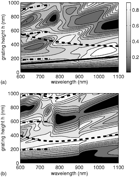 FIG. 7. Diffuse transmittance for a TiO2 ns=2.6 grating on a silicon substrate with L=900 nm, for a TE and b TM illuminations. The plots also show the maxima in diffuse transmittance expected due to inteference between the zeroth and second grating modes dashed lines , between the zeroth and fourth grating modes dash-dot lines , and Fabry-Pérot interference of the zeroth grating mode for the TE case solid line .


