A Modified Positive Velocity and Position Feedback scheme with delay compensation for improved nanopositioning performance
Summary (5 min read)
1. Introduction
- Nanopositioners generally come in two types viz: tube-type and platform-type, which predominantly employ piezoelectric actuators due to their easy control and arbitrarily fine resolution [1].
- The delay introduced not only by the displacement sensors, but also by the electronic control circuit is quantified, and it is found that there exists a linear relationship between the sampling time and the delay introduced.
- Then the methodology of design of the PVPF control scheme is extended to include such delay.
- This relaxation in the sampling rate allows the utilisation of a wider range of electronic systems to control the nanopositioner and, therefore, potentially reduce the cost associated with the electronic control circuit.
2. Background theory
- The theoretical model utilised to capture the behaviour of the nanopositioner is presented.
- First, the equations utilised to reproduce the dynamics of the flexure-hinge-based mechanism are presented, and then the different elements which contribute to the introduction of a delay are listed.
- Finally, the dependence between the delay and the sampling time is justified.
2.1. Theoretical model of the mechanical structure
- As mentioned in the introduction, the crosscoupling between the motion axes is very low and can be considered negligible, which means Gxy(s) = Gyx(s) = 0 (this hypothesis is confirmed in the section devoted to the analysis of the experimental platform).
- For practical purposes (2) is usually truncated to contain a finite number of modes.
- It is important to note that the error introduced in the model due to the truncation of the high-frequency modes, deems the Smith Predictor and direct plant dynamics inversion approach infeasible when compensating for the delay.
- In [21] it was demonstrated that the typical resonance frequency of stack PEAs is usually over 50 times greater than the first mode of vibration of the mechanical structure of the nanopositioner, and lies therefore outside the bandwidth of interest.
2.2. Theoretical model of the electrical subsystem
- The electrical subsystem of the nanopositioner is comprised of the piezoelectric drive circuit, the displacement sensor, and the electronic control circuit.
- Finally, the output of the electronic control circuit is converted to an analog signal which is applied to the piezoelectric drive circuit.
- This is known as latency and its value is always lower than or equal to the cycle time, determining, therefore, a lower bound to the achievable sampling time.
- When both delays are considered, it can be seen that the total delay introduced in the system is composed by the sum of a fixed amount produced by the latency of the system and by a variable amount determined by the sampling period.
- This architecture is highly flexible due to its integration with very popular design and control software, such as Simulink or LabView, but the sampling periods achievable with such equipment are in the range of tens of microseconds, which makes the effect of the introduced delay not negligible.
3. Traditional PVPF control scheme without delay compensation
- In order to reduce the positioning errors in a nanopositioner and to impart substantial damping to the lightly-damped resonance mode, the polynomialbased pole-placement technique [26] has been widely employed in the form of three different control schemes: resonant controller, PPF, and PVPF.
- Typically, both the damping and the tracking controllers are designed independently and sequentially [27]; damping controller first and then the tracking controller.
- However a design strategy was recently proposed in [19] in which the selection of the parameters for the PVPF controller as well as the integral gain were carried out simultaneously to achieve an optimal damping and tracking effect.
- This design criteria is met when the poles of the closed-loop system lie along a circle of radius ωn and are spaced at equal angular distances as in the low pass Butterworth filter (which is often referred to as a ”maximally flat magnitude” filter).
4. Modified PVPF control scheme with delay compensation
- In the previous section the equations for designing the traditional PVPF control scheme were presented.
- Moreover, as the delay is increased, the pair of complex poles closest to the imaginary axis are displaced towards the right half plane, reducing the overall stability of the closedloop system.
- It is important to note that, besides the reduction of the stability, the introduction of a delay displaces the location of the five designed poles from the circle with radius ωn, which means that the design criteria for the PVPF cannot be achieved (flat band response at low frequencies which rolls off above the resonant frequency).
- Controller coefficients are embedded in these constants according to (8).
- Ki that place the closed-loop poles in the desired locations and 2) obtaining controller coefficients from the Ki’s by using the inverse relations (9).
5. Experimental setup and system identification
- The hardware utilised to carry out all of the experiments is described.
- The section also provides details of the system identification procedure.
5.1. Experimental setup
- Figure 2 shows the experimental setup used in this work.
- It consists of a two-axis piezoelectric-stack actuated serial-kinematic nanopositioner designed at the EasyLab, University of Nevada, Reno, USA.
- The PC utilised is an OPTIPLEX 780 with an Intel(R) Core(TM)2 Duo Processor running at 3.167 GHz and equipped with 2GB of DDR3 RAM memory.
- Taking into account the additional 10 µs padding added in each A/D and D/A conversions (according to the technical details of the data acquisition drivers of National Instruments (NI-DAQmx)), a single channel of data acquisition will require at least a 14 µs period.
- The cross-coupling between the two axes was measured leading to a result close to -40 dB.
5.2. Identification of the experimental platform
- The experimental procedure to characterise the dynamics of the nanopositioner and the hardware utilised are presented.
- The FRFs are determined by applying a sinusoidal chirp signal (from 10 to 5000 Hz) with an amplitude of 0.2 V as input to the voltage amplifier of the x−axis and measuring the output signal in the same axis.
- It should be noted also that, since the capacitive sensor measures relative displacements from a zero point, before each experiment a new zero point is measured in order to avoid any offset in the measurements.
- The procedure utilised to obtain the transfer function of the system consists of two steps: first the dominant resonance mode of the transfer function of the system was obtained by using the subspace based modelling technique described in [28], and then the delay was adjusted by minimizing the root mean square error of the phase response.
- The effects of the different delays associated with each sampling rate are shown in Figure 4, where it can be seen that the slope of the phase response of the system is steeper as the sampling period increases.
6. Experimental results
- The experimental results obtained applying the traditional and the modified PVPF control scheme are presented.
- It is shown that, with the modified PVPF control scheme, the maximum delay admissible in the plant before encountering instability is greater than that observed using the traditional PVPF design, which allows the utilisation of slower sampling rates and cheaper equipment without a meaningful loss of performance.
6.1. Experimental results with the traditional PVPF control scheme
- Neglecting the delay present in the nanopositioning system can lead to performance degradation and stability issues in closed-loop operation.
- The PVPF controller is utilised to illustrate these issues.
- It can be seen that the experimental results are not consistent with those achieved by simulation (without delay).
- It can be seen that even in the most favorable case (with a sampling time of 30 µs) the bandwidth is very far from the resonance frequency.
6.2. Experimental results with the modified PVPF control scheme
- The effect of the delay is considered in the design of the control scheme by using the modified PVPF proposed in this article.
- Figure 6 shows the experimentally measured magnitude response of the closed-loop system for various sampling times and the simulated magnitude response for the ideal case (without delay).
- The modified PVPF control scheme is redesigned for each specific sampling time, to reduce the effects of the associated delay.
- It can be seen that the experimental results more closely match the desired flat band response than is the case when the delay is not considered.
7. Analysis of the results
- The modified PVPF scheme achieves better performance than the traditional PVPF when applied to systems with time delay.
- Additionally, the modified PVPF can be applied to a wider range of systems with different delays associated, and presents improved robustness to uncertainties in the delay of the system.
- The identified model of the experimental platform is utilised to illustrate, with numerical values, the advantages of the modified PVPF over the traditional PVPF.
- The typical method to approximate the effect of the delay is the Padé approximation [29].
- A second order Padé approximation of the delay is utilised in this work to compute the placement of the poles of the closed-loop system, and to ensure the designed poles of the controller are dominant.
7.1. Range of application of the proposed method
- As stated in section 4, the last stage in the design of the modified PVPF control scheme is to ensure the five designed poles (which lie along a circle of radius ωn, as consequence of the design procedure) are dominant over the poles introduced by the delay.
- The five designed poles are considered dominant if their proximity to the imaginary axis is greater than that of the poles introduced by delay.
- It is assumed that any meaningful pole introduced by the delay would be situated further from the imaginary axis than those introduced by the Padé approximation.
- This result suggests an upper limit on the maximum permissable delay, in this case τ = 351 µs.
- It was experimentally confirmed that the slowest admissible sampling frequency, in order to control the system, is determined by 10 times the resonant frequency.
7.2. Stability robustness
- The maximum admissible difference between the nominal delay (the value used in the controller design) and the actual delay of the system, in both the traditional and modified PVPF control schemes, is analysed.
- Unlike in the previous subsection, in which a new controller was designed for each value of delay, the control scheme is designed, as in Sections 3 and 4, and the delay increased until the system becomes unstable.
- It can be seen that, as the delay is increased, the five designed poles are displaced from their initial location in the circle of radius ωn (indicated by the dashed line).
- The modified PVPF can produce different controllers depending on the value of the nominal delay considered in the design stage.
- Figure 9 depicts the evolution of the poles of the closed-loop system with the modified PVPF control scheme designed considering a nominal delay of τ = 351 µs.
8. Conclusions
- This paper has proposed a new methodology to tune the parameters of the well-known PVPF control scheme, which allows to place arbitrarily the dominant closed-loop poles of the system, even in the presence of a time delay in the nanopositioning system.
- It has been experimentally and theoretically shown that the delay introduced in the nanopositioner is determined by the sampling rate utilised and its effects cannot be neglected.
- It has also been demonstrated that the performance of the traditional PVPF is greatly affected by the time delay introduced by the controller, i.e. the system performance deteriorates as the sampling time is increased.
- These results determine the potential utilisation of the modified PVPF with slower sampling rates, which would allow the utilisation of cheaper equipment for the electronic control circuitry, and would reduce the overall cost of the system.
Did you find this useful? Give us your feedback
Figures (9)

Figure 8. Root contours of the closed-loop system controlled with the traditional PVPF when the changing parameter is the delay of the system (Circle of radius ωn indicated in dashed line) 
Figure 9. Root contours of the closed-loop system controlled with the modified PVPF scheme scheme designed considering a nominal value of delay τ = 351 µs (indicated with crosses). The arrows in the figure indicate the moving direction of the poles when the actual delay of the plant is increased 
Figure 3. FRF of the experimental platform and the secondorder model (including time delay), measured from the input to output displacements 
Figure 2. A two-axis serial kinematic nanopositioner, designed at the EasyLab, University of Nevada, Reno, driven by two PiezoDrive 200V Linear amplifiers, with position measured by a Microsense 4810 capacitive sensor ![Figure 7. Evolution of the closed-loop poles of the experimental platform for delay in the range [0,600] µs. The position of the poles for a delay of 351 µs is indicated with crosses and diamonds.](/figures/figure-7-evolution-of-the-closed-loop-poles-of-the-ah2fa151.png)
Figure 7. Evolution of the closed-loop poles of the experimental platform for delay in the range [0,600] µs. The position of the poles for a delay of 351 µs is indicated with crosses and diamonds. 
Figure 4. Magnitude and phase response of the nanopositioning platform measured from input to output displacement for different sampling rates. Plots in blue are experimental results and plots in green are simulated results including time delay 
Figure 5. Frequency response of the experimental system without delay compensation and simulated results for the ideal case (without delay) 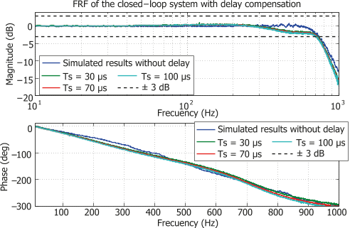
Figure 6. Frequency response of the experimental system with delay compensation and simulated results for the ideal case (without delay) 
Figure 1. Block diagram of the closed-loop PVPF control scheme with tracking


![Figure 7. Evolution of the closed-loop poles of the experimental platform for delay in the range [0,600] µs. The position of the poles for a delay of 351 µs is indicated with crosses and diamonds.](/figures/figure-7-evolution-of-the-closed-loop-poles-of-the-ah2fa151.webp)


Citations
232 citations
53 citations
Cites background from "A Modified Positive Velocity and Po..."
...It is assumed that the poles introduced by the Padé approximation are dominant with regard to the remaining poles of the delay [35]....
[...]
53 citations
Cites background from "A Modified Positive Velocity and Po..."
...g, the actuator system, the displacement sensors, the electronic control circuits, and the field networks involved in feedback loops [30], [31]....
[...]
45 citations
25 citations
References
139 citations
109 citations
"A Modified Positive Velocity and Po..." refers background in this paper
...Typically, both the damping and the tracking controllers are designed independently and sequentially [27]; damping controller first and then the tracking controller....
[...]
91 citations
"A Modified Positive Velocity and Po..." refers background or methods in this paper
...The software-dependent controllers are usually presented in the form of a traditional PC equipped with some realtime operating system and signal acquisition hardware [18, 24, 25]....
[...]
...In several works [13, 15, 17, 18, 19], (2) is truncated at the first mode as it is dominant....
[...]
80 citations
69 citations
"A Modified Positive Velocity and Po..." refers methods in this paper
...The software-dependent controllers are usually presented in the form of a traditional PC equipped with some realtime operating system and signal acquisition hardware [18, 24, 25]....
[...]