
All figures (12)
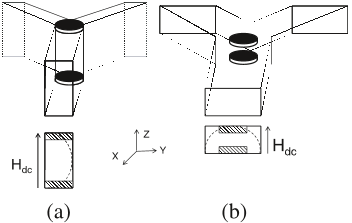 Figure 1. Geometries of E-plane and H-plane junctions of waveguide circulators. Dotted line = Electric field intensity.
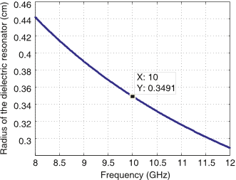 Figure 5. Radius of the dielectric resonator at different frequencies.
 Figure 6. S-parameters of single-band E-plane circulator. Dimensions: d = 3.5mm, r = 3.38mm, ferrite: TTVG-930 and internal bias: H0 = 10 Oe.
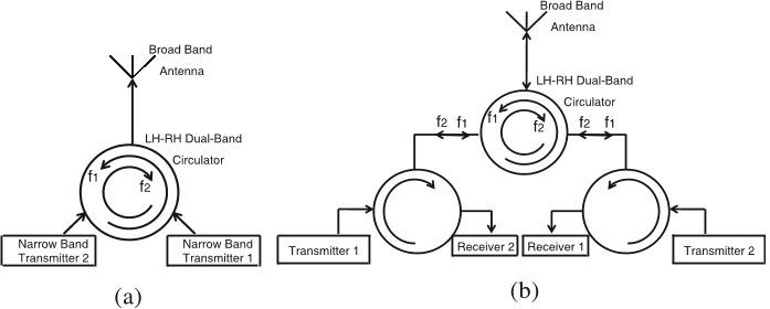 Figure 2. Schematics of two applications for LH-RH dual-band Eplane circulator.
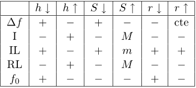 Table 2. Ferrite shape optimization (∆f (dual band frequency deviation), I (Isolation), IL (Insertion Loss), RL (Return Loss), f0 (Center Frequency)) (M means a relative maximum and m means a relative minimum).
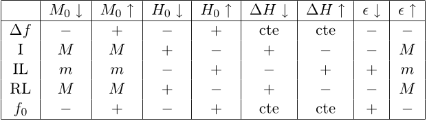 Table 1. Ferrite material parameters optimization (∆f (dual band frequency deviation), I (Isolation), IL (Insertion Loss), RL (Return Loss), f0 (Center Frequency)), (M means a relative maximum and m means a relative minimum).
 Figure 7. Shape optimization of the triangular ferrite.
 Figure 8. S-parameters of dualband E-plane circulator. Dimensions: d = 3.5mm, r = 3.38mm, ferrite: TTVG-930 and internal bias: H0 = 10 Oe.
 Table 3. Commercial ferrite parameters used in the final designs.
 Figure 9. S-parameters of dualband E-plane circulator. Dimensions: d = 3.5mm, r = 4.55mm, ferrite: Y331 and internal bias: H0 = 10Oe.
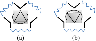 Figure 4. Geometries of two kinds of ferrite placement in the waveguide junction.
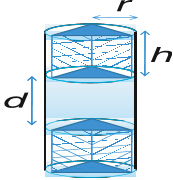 Figure 3. Physical geometry of the triangular ferrite posts and the dielectric filling around them.


