scispace - formally typeset
Search or ask a question
Proceedings ArticleDOI

A new method for start-up of isolated boost converters using magnetic- and winding-integration

TL;DR: In this paper, a new solution to the start-up and low output voltage operation of isolated boost family converters is presented, by the use of integrated magnetics and winding integration, the transformer secondary winding is re-used during startup as a flyback winding coupled to the boost inductor.
Abstract: A new solution to the start-up and low output voltage operation of isolated boost family converters is presented. By the use of integrated magnetics and winding integration, the transformer secondary winding is re-used during start-up as a flyback winding coupled to the boost inductor. The traditional added flyback winding coupled to the boost inductor is thus eliminated from the circuit, bringing substantial cost savings, increased efficiency and simplified design. Each subinterval of the converter operation is described through electrical and magnetic circuit diagrams, and the concept is extended to other isolated boost family topologies. The principle of operation is demonstrated with a 800W isolated boost prototype, and a 1600W primary parallel series secondary isolated boost converter. Efficiency measurements of both prototypes are presented, including measurements during both start-up and normal boost operation.

Summary (2 min read)

Introduction

  • Isolated boost converters have been shown to be the most efficient topology for high power, low input voltage, high output voltage applications [1]–[5].
  • Suitable applications include distributed generation systems, backup systems, fuel cell converters, electric vehicle applications and avionic applications.
  • A disadvantage of the topology is that the boost characteristic sets a lower limit for the output voltage, which introduces in-rush current during start-up from zero output voltage, as well as during fault situations such as output short circuit.
  • Fig.2 and Fig.3 respectively show the simplified and complete circuit diagrams of the new circuit topology, where the magnetic integration of the boost inductor with the transformer allows the boost inductor to couple to the secondary winding during start-up, such that the secondary winding acts as flyback winding.

II. PRINCIPLE OF OPERATION

  • Electrical circuit diagram of new start-up method.
  • Since Dsw ≥ 0.5, the phase shifted gate signals overlap such that either all switches are on, or two diagonal switches are on.
  • Known as the charging or boosting subinterval, the circuit operation during this is shown in fig.
  • 4(b), the flux rate induced by the inductor is uncoupled from the transformer windings due to the fact that the voltage drops induced on the transformer windings on each side leg are of opposite polarity.
  • When two diagonal switches are on and the other two are off, the inductor current passes through the primary winding, allowing the corresponding diagonal diode pair of the output rectifier to become forward biased.

III. EXTENSION TO OTHER ISOLATED BOOST FAMILY TOPOLOGIES

  • The concept can readily be applied to numerous isolated boost derived topologies, such as flyback- current-fed pushpull [8], dual inductor [9], and parallel primary isolated boost [3].
  • It can also be applied to various rectification circuits, including voltage doubler and center tap rectifier.
  • Df is no longer required, and the start-up functionality is gained "or free" using only the specified integrated magnetic structure, which may be beneficial in itself by reducing magnetic com- Fig. ponent count and increasing efficiency [10].
  • Figure 9 shows the principle applied to the parallel primary topology, which has been shown to be an efficient way of scaling isolated boost converter design for higher power [3], [4].

IV. EXPERIMENTAL VERIFICATION

  • An 800W isolated boost prototype as well as a 1600W parallel primary isolated boost prototype have been built in order to verify the start-up functionality, as well as to demonstrate the possibility of achieving high efficiency and high power density by application of the integration method.
  • Both converters are hard-switched, and rely on extensive interleaving to achieve a low transformer leakage inductance of 91nH and 124nH respectively.
  • Figure 11 shows current measurements during start-up mode of the isolated boost prototype.
  • C3 (blue) shows the AC component of the input current, C4 shows the AC component of the current through a high side output rectifier D1, while C1 and C2(red) show the two gate signals.
  • After C1 goes to zero, all MOSFETs are turned off, and the boost inductor current quickly drops.

A. Efficiency Measurements

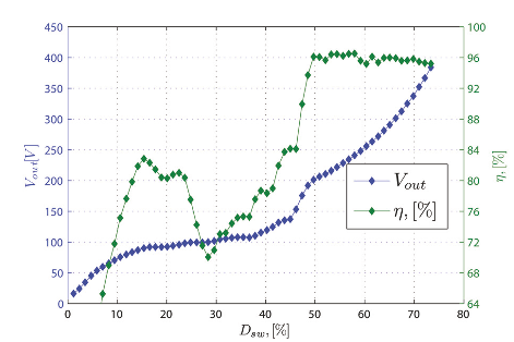
  • In order to measure the efficiency during start-up of the parallel primary prototype, the duty-cycle was gradually increased from zero to 74%.
  • Figure 12 shows the resulting efficiency measurements, as well as the measured output voltage at each duty cycle.
  • Both prototypes have a peak efficiency above 96% at the rated power, thus demonstrating the possibility of achieving high efficiency with the presented integration method.
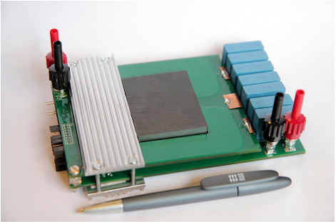
  • The parallel primary prototype is shown in fig.
  • Copper, 8 layer PCBs, with the two fullbridges mounted directly to each primary winding to minimize stray inductance.

V. CONCLUSION

  • The presented start-up method effectively addresses the start-up issue of isolated boost converters, potentially paving the way for increased industry adoption of this highly promising topology family, which so far has been limited by the startup issue.
  • The experimental work presented has focused on fuel cell applications in the kW power range, but the method may be applied to multiple other applications.
  • The constructed prototypes are hard-switched, and the fly-back mode is not optimized for high efficiency but rather for fulfilling the functional requirements of start-up without affecting normal boost mode operation efficiency.
  • Alternative applications of the method may focus on wide-range high-efficiency by employing soft-switching or regenerative snubbing, potentially making the integration method suitable for diverse applications such as Power Factor Correction and single stage inverters.

Did you find this useful? Give us your feedback

Figures (12)

Content maybe subject to copyright    Report

General rights
Copyright and moral rights for the publications made accessible in the public portal are retained by the authors and/or other copyright
owners and it is a condition of accessing publications that users recognise and abide by the legal requirements associated with these rights.
Users may download and print one copy of any publication from the public portal for the purpose of private study or research.
You may not further distribute the material or use it for any profit-making activity or commercial gain
You may freely distribute the URL identifying the publication in the public portal
If you believe that this document breaches copyright please contact us providing details, and we will remove access to the work immediately
and investigate your claim.
Downloaded from orbit.dtu.dk on: Aug 10, 2022
A New Method for Start-up of Isolated Boost Converters Using Magnetic- and Winding-
Integration
Lindberg-Poulsen, Kristian; Ouyang, Ziwei; Sen, Gökhan; Andersen, Michael A. E.
Published in:
Annual IEEE Applied Power Electronics Conference and Exposition
Link to article, DOI:
10.1109/APEC.2012.6165841
Publication date:
2012
Link back to DTU Orbit
Citation (APA):
Lindberg-Poulsen, K., Ouyang, Z., Sen, G., & Andersen, M. A. E. (2012). A New Method for Start-up of Isolated
Boost Converters Using Magnetic- and Winding-Integration. In Annual IEEE Applied Power Electronics
Conference and Exposition: Proceedings (pp. 340-345). IEEE. https://doi.org/10.1109/APEC.2012.6165841

A New Method for Start-up of Isolated Boost
Converters Using Magnetic- and
Winding-Integration
Kristian Lindberg-Poulsen
Technical University of
Denmark, Dept. of
Electrical Engineering
k.lindberg.p@gmail.com
Ziwei Ouyang
Technical University of
Denmark, Dept. of
Electrical Engineering
zo@elektro.dtu.dk
Gökhan Sen
Technical University of
Denmark, Dept. of
Electrical Engineering
gs@elektro.dtu.dk
Michael A.E. Andersen
Technical University of
Denmark, Dept. of
Electrical Engineering
ma@elektro.dtu.dk
Abstract—A new solution to the start-up and low output
voltage operation of isolated boost family converters is presented.
By the use of integrated magnetics and winding integration, the
transformer secondary winding is re-used during start-up as a
flyback winding coupled to the boost inductor. The traditional
added flyback winding coupled to the boost inductor is thus
eliminated from the circuit, bringing substantial cost savings,
increased efficiency and simplified design. Each subinterval of
the converter operation is described through electrical and
magnetic circuit diagrams, and the concept is extended to other
isolated boost family topologies. The principle of operation is
demonstrated with a 800W isolated boost prototype, and a 1600W
primary parallel series secondary isolated boost converter. Effi-
ciency measurements of both prototypes are presented, including
measurements during both start-up and normal boost operation.
I. INTRODUCTION
Isolated boost converters have been shown to be the most
efficient topology for high power, low input voltage, high out-
put voltage applications [1]–[5]. Suitable applications include
distributed generation systems, backup systems, fuel cell con-
verters, electric vehicle applications and avionic applications.
However, a disadvantage of the topology is that the boost
characteristic sets a lower limit for the output voltage, which
introduces in-rush current during start-up from zero output
voltage, as well as during fault situations such as output short
circuit.
Fig.1 shows a common solution to the start-up problem [6],
[7]. A flyback winding is arranged on the boost inductor, such
Fig. 1. Isolated full-bridge boost converter with traditional start-up method
using added external flyback winding and diode.
that the converter may operate as a flyback converter during
start-up with the associated buck-boost voltage modulation
factor allowing control of the output voltage all the way down
to zero volts. During normal boost operation, the flyback wind-
ing is completely inactive, but occupies part of the winding
window of the boost inductor, leaving less copper area for the
boost inductor, which in turn causes a drop in efficiency. Being
a power transferring magnetic component, the flyback winding
is a relatively expensive circuit element and complicates the
assembly of the boost inductor. Fig.2 and Fig.3 respectively
show the simplified and complete circuit diagrams of the new
circuit topology, where the magnetic integration of the boost
inductor with the transformer allows the boost inductor to
couple to the secondary winding during start-up, such that
the secondary winding acts as flyback winding.
II. PRINCIPLE OF OPERATION
Figures 4 to 7 explain the principle of operation as
applied to the basic full-bridge isolated boost topology. Each
Fig. 2. Electrical circuit diagram of new start-up method.
Fig. 3. Electrical and magnetic circuit diagram of new start-up method using
EI core with center leg air gap.
978-1-4577-1216-6/12/$26.00 ©2012 IEEE 340

subinterval of operation is shown with an electric circuit
diagram followed by the corresponding and a magnetic core
diagram. Relevant voltage polarities are marked with +/-
signs, and current directions are marked with arrows while
inactive elements are dimmed. The electric circuit diagrams
correspond to their respective core diagrams by the ports
marked a, b, c, d. The core diagrams include the flux rate,
dt
= φ
0
, induced by the inductor, as well as the flux rate
induced by the transformer. The circuit operation can be
understood by analysing voltage polarities and flux rates
together with the right hand rule, while taking into account
the switch states, current directions and diode bias.
Boost mode operation (D
sw
0.5)
In the familiar isolated boost topology, the full-bridge
switch duty cycle must be above 0.5, such that there is always
a current path available for the boost inductor. This is defined
as the normal boost mode operation. The gate signal is
phase-shifted 180
between each diagonal high-side/low-side
switch pair. Since D
sw
0.5, the phase shifted gate signals
overlap such that either all switches are on, or two diagonal
switches are on.
When all switches are on, V
in
is applied to the boost inductor,
and the input current is increasing. Known as the charging
or boosting subinterval, the circuit operation during this is
shown in fig. 4. As seen in fig. 4(b), the flux rate induced by
the inductor is uncoupled from the transformer windings due
to the fact that the voltage drops induced on the transformer
windings on each side leg are of opposite polarity.
The second sub-interval, referred to as the boost mode
discharge subinterval, is shown in fig. 5. When two diagonal
switches are on and the other two are off, the inductor
current passes through the primary winding, allowing the
corresponding diagonal diode pair of the output rectifier to
become forward biased. The output voltage is reflected to the
primary winding, such that a negative voltage drop is applied
over the inductor, decreasing the current. The corresponding
core diagram in fig. 5(b) shows that the inductor flux rate
is decreasing, and is still uncoupled from the transformer.
Additionally, it is noted that the flyback diode D
f
is reverse
biased.
Start-up mode operation (D
sw
< 0.5)
When the switch duty cycle is reduced below 0.5, the
diagonal switch pairs are no longer overlapping in on-state,
meaning that either two diagonal switches are on or all
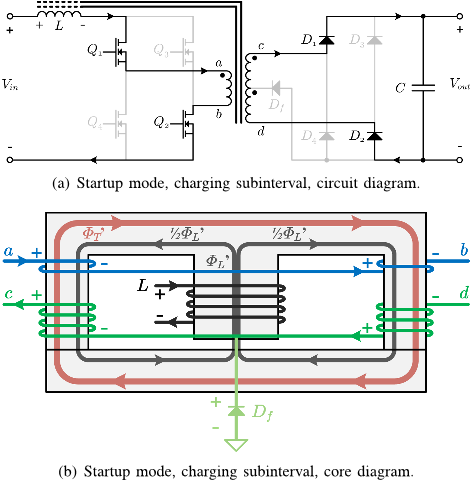
switches are off. When two switches are on, the circuit
operation is identical to the boost mode discharge subinterval,
except that the inductor current is now decreasing due to the
fact that the primary voltage is lower than the input voltage,
causing a positive voltage drop over L. Because of this,
the subinterval is referred to as the start-up mode charging
subinterval, and the corresponding circuit and core diagrams
are seen in fig. 6.
(a) Boost mode, charging subinterval, circuit diagram.
(b) Boost mode, charging subinterval, core diagram.
Fig. 4. Boost mode, charging subinterval. All switches are on, inductor
current is increasing. Core diagram shows that inductor flux rate is decoupled
from transformer.
(a) Boost mode, discharging subinterval, circuit diagram.
(b) Boost mode, discharging subinterval, core diagram.
Fig. 5. Boost mode, discharge subinterval. Two diagonal switches are on,
inductor current is decreased by transferring energy through the transformer.
It is noted that D
f
is reverse biased..
When all switches are off, there needs to be an alternative
current path such that the inductor flux remains continuous
in order to avoid MOSFET avalanche mode clamping of the
stored energy. This current path is provided by the secondary
transformer winding, which thereby acts as a flyback winding
during the flyback discharge subinterval seen in fig. 7. During
switch turn off, the inductor current is decreasing, creating a
341

(a) Startup mode, charging subinterval, circuit diagram.
(b) Startup mode, charging subinterval, core diagram.
Fig. 6. Start-up mode, charging subinterval. Two diagonal switches are on,
charging the inductor while also transferring energy through the transformer.
reverse in the flux rate, as seen by comparing φ
0
L
on fig. 6(b)
and fig. 7(b). Following the right hand rule, it is evident that
this induces respective voltage drops over each half of the
secondary winding, with polarities such as to allow D
f
to
become forward biased. The two halves of the secondary
winding will then be working in parallel to discharge the
energy stored in the air gap, with the full output voltage
applied to each winding half.
It should be noted that it would also be possible to run the
converter in "pure flyback mode", wherein either all switches
are on or all switches are off. However, this means that
zero energy is transferred to the output during the boosting
subinterval, leading to higher current ripple at same output
power. The "hybrid" startup mode shown in figs. 6 and 7 has
been described in-depth as applied to a conventional external
flyback winding [7], and the specific timing analysis of the
previous work can be directly applied to the new integrated
magnetic approach.
III. EXTENSION TO OTHER ISOLATED BOOST FAMILY
TOPOLOGIES
The concept can readily be applied to numerous isolated
boost derived topologies, such as flyback- current-fed push-
pull [8], dual inductor [9], and parallel primary isolated boost
[3]. It can also be applied to various rectification circuits,
including voltage doubler and center tap rectifier. Figure 8
shows the principle applied to an isolated boost converter with
a center tap rectifier. In this case, the flyback diode D
f
is no
longer required, and the start-up functionality is gained "or
free" using only the specified integrated magnetic structure,
which may be beneficial in itself by reducing magnetic com-
(a) Startup mode, discharging subinterval, circuit diagram.
(b) Startup mode, discharging subinterval, core diagram.
Fig. 7. Start-up mode, flyback discharge subinterval. All switches are turned
off. The drop in inductor current causes a reverse in the associated flux rate,
which couples to the secondary transformer windings. From the polarity of
the induced voltages, it is evident that this allows D
f
to be forward biased,
such that the energy stored in the air gap can be discharged to the converter
output.
Fig. 8. New start-up method applied to isolated boost with center tap
rectification circuit, where a flyback diode is not required.
ponent count and increasing efficiency [10]. Figure 9 shows
the principle applied to the parallel primary topology, which
has been shown to be an efficient way of scaling isolated boost
converter design for higher power [3], [4]. Additionally, the
shown implementation features a shared center leg for flux
cancellation, resulting in increased efficiency [11]. It is noted
that only a single flyback diode is required, regardless of the
degree of paralleling.
Additional applications include dual inductor isolated boost
and Weinberg/push-pull isolated boost topologies.
IV. EXPERIMENTAL VERIFICATION
An 800W isolated boost prototype as well as a 1600W
parallel primary isolated boost prototype have been built
in order to verify the start-up functionality, as well as to
demonstrate the possibility of achieving high efficiency and
high power density by application of the integration method.
Both converters are hard-switched, and rely on extensive
interleaving to achieve a low transformer leakage inductance
342

Fig. 9. New start-up method applied to parallel primary isolated boost
topology.
of 91nH and 124nH respectively. The converters are designed
for fuel-cell application, where a fuel cell output voltage of
25-35V is expected.
Figure 11 shows current measurements during start-up mode
of the isolated boost prototype. The converter is running at
V
in
= 25V , D
sw
= 40%, V
out
= 60V and 100Ω load. C3
(blue) shows the AC component of the input current, C4(green)
shows the AC component of the current through a high side
output rectifier D
1
, while C1(yellow) and C2(red) show the
two gate signals.
When the gate signal C1(yellow) is high, D
1
and D
3
are
forward biased, conducting a constant current through the
secondary winding to the load. During this period, the boost
inductor current C3(blue) is rising. After C1(yellow) goes to
zero, all MOSFETs are turned off, and the boost inductor
current quickly drops. At this moment, current continues
flowing through D
1
, safely discharging the energy stored in
the boost inductor to the output. In fig. 11, C4(green) shows
the current of the flyback diode D
f
, clearly demonstrating the
commutation of the boost inductor current.
Fig. 10. Currrent waveforms of isolated boost prototype during startup mode.
C3 (blue) shows the AC component of the input current, C4(green) shows the
current through a high side output rectifier D
1
, while C1(yellow) and C2(red)
show the two gate signals.
Fig. 11. Currrent waveforms of isolated boost prototype during startup mode.
C3 (blue) shows the AC component of the input current, C4(green) shows the
current through the flyback diode D
f
, while C1(yellow) and C2(red) show
the two gate signals.
A. Efficiency Measurements
In order to measure the efficiency during start-up of the par-
allel primary prototype, the duty-cycle was gradually increased
from zero to 74%. A fixed load of 100Ω is used across the
range, corresponding to the rated 1600W at V
out
= 400V .
Figure 12 shows the resulting efficiency measurements, as
well as the measured output voltage at each duty cycle. The
local maximum of efficiency around D
sw
= 20% is caused
by discontinuous conduction mode. Close to D
sw
= 50%, the
efficiency rises dramatically, as an increasingly greater propor-
tion of the total power is transferred through the transformer
rather than the flyback operation. The converter is capable of
operating continuously in start-up mode without overheating,
and the voltage transitions smoothly across D
sw
= 50%.
The efficiency during normal operation was measured for
both the 800W isolated boost prototype and the 1600W
parallel primary. Figure 13 shows the isolated boost prototype
measurements, while fig. 12 shows the results for the parallel
primary prototype. Both prototypes have a peak efficiency
Fig. 12. Efficiency measurements of parallel primary prototype, showing
efficiency and output voltage as a function of duty cycle, with a fixed load
of 100Ω.
343

Citations
More filters
01 Jan 2014
TL;DR: In this article, the authors presented the design of a high efficiency dc-dc converter developed and optimized for bidirectional fuel cell applications, which was part of the PhD project entitled "High Efficiency Reversible Fuel Cell Power Converter".
Abstract: The large scale integration of renewable energy sources requires suitable energy storage systems to balance energy production and demand in the electrical grid. Bidirectional fuel cells are an attractive technology for energy storage systems due to the high energy density of fuel. Compared to traditional unidirectional fuel cell, bidirectional fuel cells have increased operating voltage and current ranges. These characteristics increase the stresses on dc-dc and dc-ac converters in the electrical system, which require proper design and advanced optimization. This work is part of the PhD project entitled "High Efficiency Reversible Fuel Cell Power Converter" and it presents the design of a high efficiency dc-dc converter developed and optimized for bidirectional fuel cell applications. First, a brief overview of fuel cell and energy storage technologies is presented. Different system topologies as well as different dc-ac and dc-dc converter topologies are presented and analyzed. A new ac-dc topology for high efficiency data center applications is proposed and an efficiency characterization based on the fuel cell stack I-V characteristic curve is presented. The second part discusses the main converter components. Wide bandgap power semiconductors are introduced due to their superior performance in comparison to traditional silicon power devices. The analysis presents a study based on switching loss measurements performed on Si IGBTs, SiC JFETs, SiC MOSFETs and their respective gate drivers. Magnetic components are a fundamental part in most power converters and have a significant impact on power converters performance and cost. After basic introduction on magnetic components, planar magnetics are evaluated for fuel cell (high current) applications as possible candidate for reducing the cost of magnetic components especially for large production volumes. At last, the complete converter design is presented in detailed and characterized in efficiency terms. Both benefits, provided by SiC power devices and by a redesign of the converter layout increased the converter power density up to 2.2 kW/l, achieving efficiency above 98%. A flyback derived topology designed for low power high voltage applications is also presented as a side task in connection to the PhD project.

3 citations

Dissertation
13 Jul 2018
TL;DR: The design and construction of a prototype converter is presented with a particular focus on ensuring operability of the converter over the entire fuel cell characteristic range as well as achieving high efficiency at nominal load.
Abstract: The growing demands for electrical capacity on future more electric aircraft (MEA) has led the engine-based generators to increase in size. Many manufacturers and researchers have a strong interest in developing fuel cells for aerospace applications due to their advantage of high efficiency and their use as a medium for clean energy resources. A particular interest is in using fuel cells within the Auxiliary Power Unit (APU) - a function that is currently provided by an additional gas turbine in most aircraft. Their integration into aircraft systems is not straightforward. A particular challenge, which this thesis addresses, is the provision of a suitable power conversion system which is able to interface the fuel cell to the aircraft electrical system – taking account of the complex electrical characteristics of the fuel cell and the demanding requirements of the aircraft electrical network. The interleaved boost converter with coupled inductors (IBCI) is one of the many converters that is promising for fuel cell applications because it has low input current ripple and a high step-up voltage gain. It comprises a current doubler circuit, voltage doubler rectifier, coupled inductor and active clamp. The proposed converter is an extended version of the single phase to multiphase IBCI converter using interleaving techniques. The input stage of the converter is a coupled inductor which connected to a half-bridge configuration and an active clamp. The output side is a voltage doubler rectifier. A detailed analysis of the converter and associated modelling are presented. The design and construction of a prototype converter is presented with a particular focus on ensuring operability of the converter over the entire fuel cell characteristic range as well as achieving high efficiency at nominal load. A laboratory-scale (1/10) prototype of a nominal full-scale converter was built to verify the feasibility of the proposed converter topology. Good agreement between the experimental results and the simulation results has been demonstrated, which validates the converter design, modelling, and effectiveness of the efficiency evaluation approximations.

2 citations

Proceedings ArticleDOI
Chi Xu1, Hongbin Yu1, Yunjie Gu1, Pengfei Sun1, Wuhua Li1, Xiangning He1, Fengwen Cao 
01 Sep 2014
TL;DR: The generation mechanism of the surge current is analyzed, through which the duty cycle control scheme is proposed and without an auxiliary start-up circuit, the converter can safely start up with controllable peak current value by using this method.
Abstract: When operating in island mode, DC-based microgrid mainly starts up through batteries and bidirectional DC-DC converters. In conventional way, an extra start-up circuit is required to limit the surge current, which not only decreases the efficiency but also increases the cost. In this paper, the generation mechanism of the surge current is analyzed, through which the duty cycle control scheme is proposed. Without an auxiliary start-up circuit, the converter can safely start up with controllable peak current value by using this method. Detailed analysis and formula derivation of the scheme in different operation modes are presented and the simulation and experimental results are exhibited to verify the effectiveness of the scheme, which provides a simple, safe and economic way for black start-up.

2 citations


Cites background from "A new method for start-up of isolat..."

  • ...During normal boost operation, the flyback winding is completely inactive, but occupies part of the winding window of the boost inductor, leaving less copper area for the boost inductor, which in turn causes a drop in efficiency [15]....

    [...]

Proceedings ArticleDOI
01 May 2017
TL;DR: In this paper, a novel start-up method for an isolated full-bridge boost converter with modified phase shift technique, for RES and automotive applications is proposed, in order to avoid the high inrush currents, the converter is operated in flyback mode at startup.
Abstract: A novel start-up method for an isolated full-bridge boost converter with modified phase-shift technique, for RES and automotive applications is proposed. In order to avoid the high inrush currents, the converter is operated in flyback mode at start-up. For precharging the output capacitor no auxiliary circuits or modified switching strategy is necessary. All the power switches of the isolated boost converter are soft switched (ZVS or ZCS), for the whole duty cycle. One single control circuit is used for control, protection and start-up. The voltage-fed control circuit is modified to be applied to the current-fed full-bridge DC-DC converter.

1 citations

Journal ArticleDOI
TL;DR: In this paper, the authors proposed a new operation mode for extending the input and output voltage range in PPIBC, which does not modify the power stage and only shortcircuits one of the parallel connected primary windings in the topology.
Abstract: DC-DC converters for fuel cell applications require wide voltage range operation due to the unique fuel cell characteristic curve. Primary parallel isolated boost converter (PPIBC) is a boost derived topology for low voltage high current applications reaching an efficiency figure up to 98.2 %. This paper proposes a new operation mode for extending the input and output voltage range in PPIBC. The proposed solution does not modify PPIBC power stage; the converter gain is modified by short-circuiting one of the parallel connected primary windings in the topology. The change in operation mode divides by two the converter input-to-output voltage gain. This allows covering the conditions when the fuel cell stack operates in the activation region (maximum output voltage) and increases the degrees of freedom for converter optimization. The transition between operating modes is studied because represents a change in the converter steady-state conditions. A solution is proposed based on pre-calculation of the duty cycle prior to the transition. DOI: http://dx.doi.org/10.5755/j01.eee.20.5.7107

Cites background from "A new method for start-up of isolat..."

  • ...The state of the art solution for extended voltage range in isolated boost converters has been presented in the literature [3], [7]....

    [...]

References
More filters
Journal ArticleDOI
TL;DR: A new design approach achieving very high conversion efficiency in low-voltage high-power isolated boost dc-dc converters is presented, demonstrating that an extensive interleaving of primary and secondary windings is needed to avoid high winding losses.
Abstract: A new design approach achieving very high conversion efficiency in low-voltage high-power isolated boost dc-dc converters is presented. The transformer eddy-current and proximity effects are analyzed, demonstrating that an extensive interleaving of primary and secondary windings is needed to avoid high winding losses. The analysis of transformer leakage inductance reveals that extremely low leakage inductance can be achieved, allowing stored energy to be dissipated. Power MOSFETs fully rated for repetitive avalanches allow primary-side voltage clamp circuits to be eliminated. The oversizing of the primary-switch voltage rating can thus be avoided, significantly reducing switch-conduction losses. Finally, silicon carbide rectifying diodes allow fast diode turn-off, further reducing losses. Detailed test results from a 1.5-kW full-bridge boost dc-dc converter verify the theoretical analysis and demonstrate very high conversion efficiency. The efficiency at minimum input voltage and maximum power is 96.8%. The maximum efficiency of the proposed converter is 98%.

303 citations

Proceedings ArticleDOI
06 Oct 1996
TL;DR: In this paper, the authors compared two current-fed push-pull DC-DC power converters: the isolated boost and an alternative topology named as the dual inductor pushpull power converter (DIC).
Abstract: This paper compares two current-fed push-pull DC-DC power converters: the current-fed push-pull power converter or isolated boost and an alternative topology named here as the dual inductor push-pull power converter (DIC). Since this latter converter has just one primary winding, the voltage across the main switches is reduced to the half of that in the isolated boost topology; the average current in the input inductors is also halved and the RMS current in the output capacitor is smaller. The overall efficiency is increased and the power converter's volume is reduced in the DIC converter. These and other improved design characteristics make this alternative topology more attractive than the isolated boost for equivalent applications. Analytical equations, output characteristic curves and computer simulations of both power converters are compared. An experimental breadboard of 480 W power has been assembled in order to verify the performance of the DIC power converter. The main results are provided.

122 citations


"A new method for start-up of isolat..." refers background in this paper

  • ...The concept can readily be applied to numerous isolated boost derived topologies, such as flyback- current-fed pushpull [8], dual inductor [9], and parallel primary isolated boost [3]....

    [...]

Journal ArticleDOI
TL;DR: Two new start-up schemes for isolated full-bridge boost converters are proposed and their control timing is investigated, which is compatible with pulse-width modulated (PWM) control timing for normal boost mode operation.
Abstract: Two new start-up schemes for isolated full-bridge boost converters are proposed in this paper. The control timing for each scheme, which is compatible with pulse-width modulated (PWM) control timing for normal boost mode operation, are investigated. Design considerations on the relationship between the turns ratios of the boost choke windings and the main transformer windings, and its effects on the operation of the converter, are studied. The two proposed start-up schemes are experimentally verified on a 1.6 kW, 12 V/288 V prototype.

114 citations

Proceedings ArticleDOI
06 Feb 2000
TL;DR: Two new start-up schemes for isolated full-bridge boost converters are proposed and their control timing is investigated, which is compatible with the PWM control timing for the normal boost mode operation.
Abstract: Two new start-up schemes for isolated full-bridge boost converters are proposed in this paper. The control timing for each scheme, which is compatible with the PWM control timing for the normal boost mode operation, is investigated. Design considerations on the relationships between the turns ratios of the boost choke windings and the main transformer windings, and its effects on the operation of the converter, are studied. The two proposed start-up schemes are experimentally verified on a 1.6 kW, 12 V/288 V prototype.

64 citations


"A new method for start-up of isolat..." refers background or methods in this paper

  • ...1 shows a common solution to the start-up problem [6], [7]....

    [...]

  • ...6 and 7 has been described in-depth as applied to a conventional external flyback winding [7], and the specific timing analysis of the previous work can be directly applied to the new integrated magnetic approach....

    [...]

Journal ArticleDOI
TL;DR: A high efficient planar integrated magnetics (PIM) design approach for primary parallel isolated boost converters is presented, due to a low reluctance path provided by the shared I-core, the two transformers as well as the two input inductors can be integrated independently, reducing the total ferrite volume and core loss.
Abstract: A highly efficient planar integrated magnetic (PIM) design approach for primary-parallel isolated boost converters is presented. All magnetic components in the converter, including two input inductors and two transformers with primary-parallel and secondary-series windings, are integrated into an E-I-E-core geometry, reducing the total ferrite volume and core loss. The transformer windings are symmetrically distributed into the outer legs of E-cores, and the inductor windings are wound on the center legs of E-cores with air gaps. Therefore, the inductor and the transformer can be operated independently. Due to the low-reluctance path provided by the shared I-core, the two input inductors can be integrated independently, and also, the two transformers can be partially coupled to each other. Detailed characteristics of the integrated structure have been studied in this paper. AC losses in the windings and the leakage inductance of the transformer are kept low by interleaving the primary and secondary turns of the transformers substantially. Because of the combination of inductors and transformers, the maximum output power capability of the fully integrated module needs to be investigated. Winding loss, core loss, and switching loss of MOSFETs are analyzed in-depth in this work as well. To verify the validity of the design approach, a 2-kW prototype converter with two primary power stages is implemented for fuel-cell-fed traction applications with 20-50-V input and 400-V output. An efficiency of 95.9% can be achieved during 1.5-kW nominal operating conditions. Experimental comparisons between the PIM module and three separated cases have illustrated that the PIM module has advantages of lower footprint and higher efficiencies.

64 citations


"A new method for start-up of isolat..." refers background in this paper

  • ...Additionally, the shown implementation features a shared center leg for flux cancellation, resulting in increased efficiency [11]....

    [...]