
All figures (18)
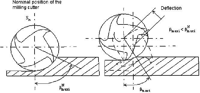
Fig. 8 An influence of the tool deflection on its maximum immersion angle 
Fig. 9 An initialisation of the tool estimated position in a given section in steady state Fig. 10 The basic algorithm in the steady state 
Fig. 11 The thickening of the number of sections at the time of a transition zone passage 
Fig. 12 The definition of the first calculation section 
Fig. 21 The error profile between the cloud of simulated and measured dots 
Fig. 19 The simulation of deflection of the machined surface 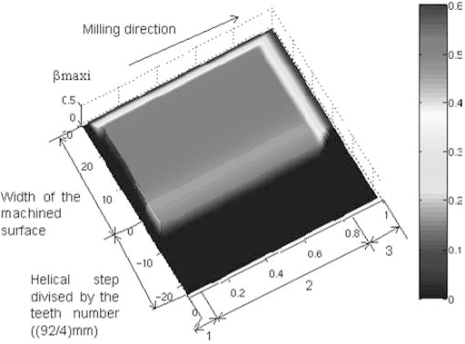
Fig. 20 The maximal engagement card 
Fig. 18 The calculated profile in the steady mode 
Fig. 1 The place of the generating points 
Fig. 2 The evolution of the generating point of a tool 
Fig. 14 The tool deflection model: approximation by a polynomial curve 
Fig. 13 The complete prediction algorithm 
Fig. 3 The deflection model definition Fig. 4 The calculation of the resulting deflection dy at point P 
Fig. 16 The definition of an engagement line Fig. 17 The validation of the identification protocol 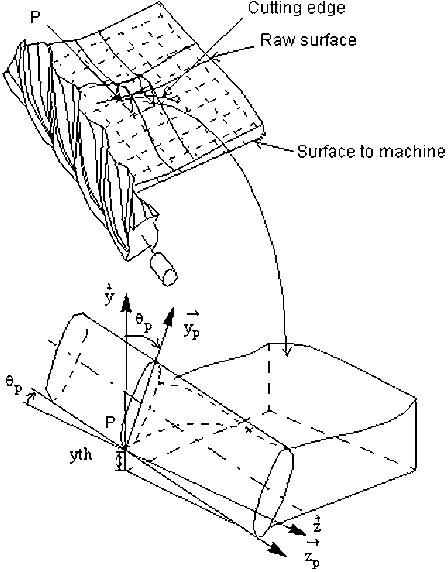
Fig. 15 The local reference mark of the milling cutter 
Fig. 6 A simulation of the machined surface 
Fig. 5 The part for the calibration of the tool workpiece material couple 
Fig. 7 A comparison of the simulated and machined surfaces


