HAL Id: hal-00098361
https://hal.archives-ouvertes.fr/hal-00098361
Submitted on 16 Feb 2018
HAL is a multi-disciplinary open access
archive for the deposit and dissemination of sci-
entic research documents, whether they are pub-
lished or not. The documents may come from
teaching and research institutions in France or
abroad, or from public or private research centers.
L’archive ouverte pluridisciplinaire HAL, est
destinée au dépôt et à la diusion de documents
scientiques de niveau recherche, publiés ou non,
émanant des établissements d’enseignement et de
recherche français ou étrangers, des laboratoires
publics ou privés.
Prediction of the machining defects in ank milling
Arnaud Larue, Bernard Anselmetti
To cite this version:
Arnaud Larue, Bernard Anselmetti. Prediction of the machining defects in ank milling. International
Journal of Advanced Manufacturing Technology, Springer Verlag, 2004, Vol. 24/1-2 (1), pp. 102-111.
�10.1007/s00170-003-1774-z�. �hal-00098361�

A. Larue, B. Anselmetti
A prediction of the machining defects in flank milling
Abstract In peripheral milling with great axial engage-
ments, the tool deflections generate some geometrical
defects on the machined surface. This article present a
prediction method of these defects which is applicable
on every ruled surface. The cutting forces are estimate
with the cutting pressure notion. The parameters of the
tool/workpiece material couple are identified by a test
part. The prediction of the tool deflections requires
controlling the tool immersion angle for each angular
position of the tool. The deflections can be significant.
An original procedure which is based on an engagement
cards avoids an iterative calculation of the radial
engagement. The experimental checking of the method
of prediction is presented in a test.
Keywords Peripheral milling Æ Tool deflections Æ
Identification of a tool workpiece material couple Æ
Engagement cards
1 Introduction
1.1 Prese ntation
The present stud y is about flank milling using the long
cutters of free forms. This free forms are made up of
ruled surfaces. This very powerful process, from a pro-
ductivity and surface quality point of view, is very
popular in aeronautics and mould manufacturing.
The magnitude of the defect induced by the deflection
of a long HSS cutter with a diameter of 20 mm can reach
0.7 mm for a radial engagement of 3 mm. Such geo-
metrical variations induce the nonrespective of the part
specifications.
The purpose of this article is to establish a prediction
method of flank milling defects at low speeds which can
be integrated in a computer aided sesign and manufac-
turing software (CAD/CAM).
The characterisation of the tool deflections is based
on a cutting pressure model. The model parameters are
gauged by milling a test part on the production machine
tool. When the tool workpiece coupl e is identified, the
influence of the tool deflection on the part geometrical
defects can be predicted.
1.2 The problem
To predict tool deflection, it is necessary to control the
engagement of the cutting edges into the workpiece
material at every moment.
At high cutting speed, chatter vibration phenomena
appears [1, 2]. To model that phenomena, lots of re-
search took the mass, the damping and the acceleration
of the milling structure into account [3, 4, 5, 6]. These
studies allow the prediction of the vibratory behaviour
of the structure. First ly, they result in long calculations
which are difficult to implement in a CAD/CAM system
on all the surfaces to machine. Secondly, such studies
require a dynamical protocol to identify the dynamical
structure characteristics and the force model parameters.
Our objective at low speed milling was to predict the
surface defects and to compensate for the tool paths. We
also needed a model whic h was easy to identify and fast
to use. We showed that a satisfying result can already be
obtained without taking the vibratory behaviour into
account [7]. That’s why the calculation of surface defects
thus passes by the motion study of the generating point
of each cutting edges in catch in the workpiece material.
In fact, the surface is generated by the cutter sweep-
ing. Each rule of the surface is obtained by the gener-
ating point displacement along the helicoidal cutting
edge during the rotation of the cutter.
A. Larue (&)
LURPA Ecole Normale Supe
´
rieure de Cachan,
61 Av Pt Wilson, 94235 Cachan Cedex, France
E-mail: larue@lurpa.ens-cachan.fr
Tel.: +33-1-47402765
Fax: +33-1-47402220
B. Anselmetti
Institut Universitaire de Technologie de CACHAN,
9 avenue de la division, Leclerc 94234 Cedex, France
1

The tool deflection can be calculated at every moment
using a model resulting from the materials resistance
theory (RdM).
The cutting forces applied to the tool thus depend on
the number of teeth in catch and on the length of the
cutting edge engaged in the workpiece material at every
moment.
It is thus necessary to calculate the immersion angles
for each cutting edge starting from the finished surface
and from the rough surface defined by the CAD model.
This calculation must be carried out for each rule and
for each angular position of the cutt er.
During our tests, we have showed that the deflections
are so significant that it is absolutely necessary to take
the deflection into account to calculate the cutting edge
engagement. In the first approach, this analysis requires
considering an iterative calculation process which is very
expensive in terms of computation times. The article’s
purpose is to establish a precise process, which avoids
this iterative calculat ion in the majority of the cases. It
presents the engagement card concept which represents
the tool load during the milling.
2 The modelisation of surface defects
2.1 The surface generation
The problem studied is the peripheral milling of a ruled
surface. Our interest is focused on the down milling case.
At first approximation, the tool path is generated so that
during that time, the cutter generatrix is combined with
the various rules of the surface. However, the surface
concavity is not constant along the rule. Various tech-
niques of the cutter axis shifting make it possible to
improve the milling quality by limiting the undercut and
the overcut [8, 9, 10, 11].
This work thus considers that the CAM system
constructs the tool path generation and gives the tool
axis (axis ~z position A
n
and the normal to the machined
surface
~
y at every moment, which makes it possible to
define the cutting section S
n
at the curvilinear abscissa
S
a
n
along the directrix (Fig. 1).
~
x completes the trihedral
~
x,
~
y, ~z in the feed direction.
In this section, we will suppose that the generatrix to
machine is the line D
n
. Our objective is thus to determine
the variations of the machined surface position com-
pared with the theoretical line D
n
. These variations are
added to the undercut and overcut defects. The different
sections will be studied with a ‘‘normal’’ step and a
‘‘reduced’’ step. The reduced step will be used when
some engagement discontinuities are detected on the
machined surface or on the rough surface.
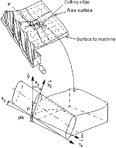
The generating point of a tool is mobile on the line
D
n
. At moment t, the generating point is in P at distance
z of the tool holder which is supposed to provide a
perfect embedding. It is thus necessary to know the tool
deflection in P which will be equal to the surface position
variation in this point.
At moment t+dt, the generating point is in P’ at the
distance z’ (Fig. 2).
The deflection varies according to the generating
point P, which generates a deformed profile on the
surface.
2.2 The deflection model
Our deflection model correspond to an extension of the
Kline and DeVor model [12], which has involved lots of
semi static models [13, 14, 15].
At a given moment, the generating point is in P. Each
elementary length of the cutting edges in catch in the
workpiece generates an elementary tool deflection in
P. The sum of these deflections gives the variation of the
surface in P.
At point Q located along the cutting edge, the
angular position is b. The force applied in Q on a part of
the cutting edge, whose elementary length is dz, consists
Fig. 1 The place of the generating points
Fig. 2 The evolution of the generating point of a tool
2

of a tangential compone nt dFt and a radial component
dFr.
The cutting forces are obtained with the following
model:
dFr ¼ Kr ep dz ¼ Kr
0
fz sin bðÞdz
=
fz sin bðÞðÞ
0:3
ð1Þ
ep is the depth of cut given by: ep ¼ fz sin bðÞ.
fz is the feedrate per tooth.
Kr ¼ Kr
0
ep
0:3
and Kt ¼ Kt
0
ep
0:3
ð2Þ
The cutting pressures Kr
0
and Kt
0
are characteristics
of the tool workpiece material couple. They are deter-
mined by an identification test.
Only the normal component dN of the cutting force
acts on the mac hined surface deformation (Fig. 3):
dN bðÞ¼dFr bðÞcos bðÞþdFt bðÞsin bðÞ
In P, the resulting deflection dy induced by the force
dN appl ied to point Q is given by a simple model of a
fixed beam of the constant quadratic moment of inertia:
I
Gy
(Fig. 3).
dy ¼
1
E I
Gy
dN bðÞ
z L bðÞðÞ
3
3
!
þ
z L bðÞðÞ
2
L bðÞ
2
!"#
ð3Þ
where L bðÞ
¼h b
=
2pðÞis the distance between P and
Q for the tooth which leaves its trace on the part, h being
the helicoidal milling cutter step.
A similar relation is defined for the points Q which
belong to the following cutting edge in catch (when Q
is on the left of P).
For each point P, the theoretical total deflection is the
sum of the elementary deflections generated by all the
points Q of the cutting edges simultaneously engaged in
the workpiece material.
yth ¼
X
Nc
k¼1
Z
b
maxi
b
mini
dy
k
0
B
@
1
C
A
ð4Þ
where Nc is the number of cutting edges in catch.
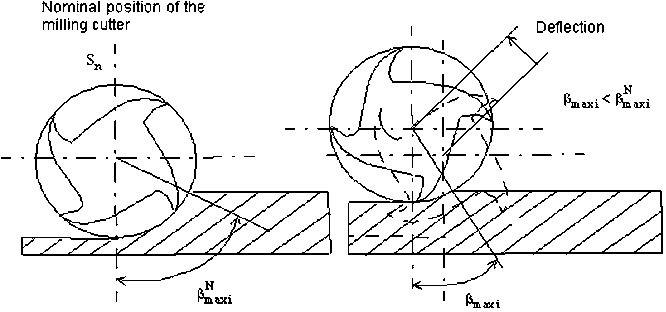
The difficulty of the calculation lies in the definition
of the maximal and minimal immersion tool angles
(b
maxi
and b
mini
). The se angles are defined by the inter-
section of the screw which characteri ses the tool cutting
edge when the generating point is in P. b
maxi
corre-
sponds to the intersection with the rough surface. b
mini
corresponds either to the intersection with the finished
surface (b
mini
=0), or to the intersection with the side
of the part 06b
mini
6b
maxi
ðÞ. This calculation will be
developed in pa ragraph 4, because it should take the
tool deflection into account. Figure 4 shows the calcu-
lation of the resulting deflection dy at point P.
2.3 The identification of the coefficients
To determine the coefficients Kr
0
and Kt
0
, an identifi-
cation protocol on an unspecified industrial milling
machine was proposed [7, 16, 17]. The identification
procedure consists in the down peripheral milling of a
plan starting from the test part defined in Fig. 5. The
width of the part is slightly higher than
h
Z
where h is the
tool helicoı
¨
dal pitch and Z is the total number of teeth.
The radial depth of cut varies gradually from 0.5 to
3 mm (Fig. 5). The tool end is left free so as to make it
possible to stud y only the influence of the helicoidal
cutting edge on the part defect.
From an operational point of view, the identification
procedure consists in milling the test part and measuring
the defects of the machined surface.
The immersion angles can be calculated by taking the
tool deflection which is estimated starting from the
measured dots into account.
The coefficients Kr
0
and Kt
0
are calculated by mini-
mising the sum of the squares of the differences between
the dots measured and the dots simulated.
Fig. 3 The deflection model definition Fig. 4 The calculation of the resulting deflection dy at point P
3

2.4 The identification of the tool workpiece material
couple
For our application, the conditions of the identification
test are the following:
HSS tool of diameter 20 mm, whose active length is
88 mm—4 teeth:
– Machined workpiece material: C48
– Milling on a vertical milling centre
– Vc=25 m/min
– fz=0.2 mm/tooth
With I
Gy
=7,854 mm
4
, the coefficients calculated are:
Kr
0
¼ 312
Kt
0
¼ 120
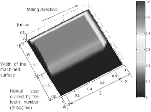
The simu lated machine surface is illustrated in Fig. 6.
Several tests showed that these coefficients are almost
independent from the cutting speed.
Figure 7 shows that the difference between the sim-
ulated and the cloud of theoretical dots lie for 95 percent
of the surface between ±0.05 mm.
3 The prediction of the milling defects in CAM
3.1 Introdu ction
The work objective is to predict the form and the posi-
tion variations of the flank machined surfaces. These
variations are due to the too l deflections generated by
the variable cutting forces. The part deformations and
the machine deformations are not taken into account.
These cutting forces are depending on the cutter
immersion angle at every moment which also consider-
ably depends on the tool deflection, which makes the
calculation difficult (Fig. 8).
In front of this problem, we propose a defects pre-
diction method which is applicable in a CAD environ-
ment for the milling of an unspecified ruled surface. The
final geometry to obtain is thus defined by a CAD
model. The tool paths are initially given by the CAD for
example with the use of tool laying techniques on a
surface, suggested by Rubio [8], To
¨
nshoff [9] and
Affouard [10].
By misnomer, we call the ‘‘rough’’ surface of the part
the part surface before the tool passes. This raw part can
be described by a CAD model or by a raw management
dynamical system according to the tool paths during the
preceding operations (NCSIMUL software [18], Vericut
software [19] and Delmia software [20]). In all cases, the
radial engagement is supposed to be lower than the
cutter diameter: ap £ 2·R, in order to exclude the mill-
ing in full matter.
3.2 The prediction algorithm in steady mode
An iterative solution would firstly consist in calculating
the cutter deflection by considering the theoretical angle
Fig. 5 The part for the calibration of the tool workpiece material
couple
Fig. 6 A simulation of the machined surface
Fig. 7 A comparison of the simulated and machined surfaces
4


