Acoustic matching of a traveling-wave thermoacoustic electric generator
Summary (4 min read)
1. Introduction
- Traveling-wave thermoacoustic electric generator is capable of converting thermal energy into electric power with high reliability and efficiency with very simple structures.
- After further optimizations, the system was able to achieve 473.6 W electric power and 14.5% thermal-to-electric efficiency [17].
- Therefore, the match of the acoustic impedances between the thermoacoustic engine and the linear alternator is critical to the overall performance.
- The effects of the acoustic impedance on the performance of the thermoacoustic system and whether the systems were acoustically well matched have not been studied by the above work.
2. Procedure of acoustic impedance match
- Acoustic impedance denotes the ratio of pressure to volume flow rate in acoustic systems, such as thermoacoustic engines, pulse tube refrigerators, etc. Acoustic impedance Za is defined by, UpUpaaa U p j U p U p ZjZZ sincosImRe 1 1 1 1 1 1 (1) where, 1p and 1U denote the complex pressure amplitude and volume flow rate amplitude, respectively;.
- Up is the phase difference between the pressure and volume flow rate.
- When the acoustic impedance is matched in a thermoacoustic electric generator, it means that the thermoacoustic engine and the linear alternators can both work at or near their optimal working conditions simultaneously when they are connected.
- Secondly, the required acoustic impedances to reach the optimal performances of the engine and the alternators should be matched.
- In electrics, an effective way of realizing the electric impedance match in a power circuit is to introduce the concepts of input impedance of the electric load and the output impedance of the electric source, and design the load and electric source separately.
3. Experimental Setup
- Figure 2 illustrates the schematic of the traveling-wave thermoacoustic engine [17].
- The regenerator (REG) is the key component where thermoacoustic energy conversion happens, and is filled with stainless steel screens with a mesh number of 120.
- The main ambient heat exchanger (MAHX) is of shell-tube type with working gas oscillating inside the stainless steel tubes with inner diameters of 2 mm and the chilling water flowing through the shell sides.
- The schematic of the linear alternators, which are supplied by Lihan Thermoacoustic Technologies Co. Ltd, are depicted in Figure 3.
- The generated electric power is therefore dissipated by the load resistance.
4. Output acoustic impedance of thermoacoustic engine
- Requirements of acoustic impedances for coupling the engine and the load are different at different output positions.
- Therefore, the output acoustic impedance characteristics can be simply modulated by changing the location for connecting the load.
- A numerical model of the traveling-wave thermoacoustic engine is first built based on DeltaEC (Design Environment for Low-amplitude ThermoAcoustic Energy Conversion) [31].
- The output acoustic power, thermoacoustic efficiency, pressure amplitude, volume flow rate, and frequency at different acoustic impedances can then be calculated by setting different values of the real and imaginary parts of the BRANCH component.
- In the calculations, the hot and ambient heat exchangers are set at 650 °C and 13 °C, respectively.
4.1 Operating frequency
- Figure 4 shows the variation of operating frequency of the thermoacoustic engine with the output impedance at the two output locations.
- It is shown that the output acoustic impedance has weak effects on the operating frequency, especially at relatively high acoustic impedances.
- In general, the operating frequencies of the engine are around 65.5 Hz.
4.2.1 Location A
- Variations of the output acoustic power and thermoacoustic efficiency of the thermoacoustic engine with the acoustic impedance at location A are given in Figure 5(a) and Figure 6(a), respectively.
- It is both beneficial for the power and the efficiency if the imaginary part Im[Za] of the output acoustic impedance approaches zero, which means the acoustic load is a pure acoustic resistance.
- Increasing the magnitude of Im[Za] results in a decrease of the maximum output acoustic power and the thermoacoustic efficiency, especially the latter one.
- The required output acoustic impedances of the engine for the maximum output acoustic power and thermoacoustic efficiency are not the same, and a compromise should be made when modulating the acoustic impedance of the load.
4.2.2 Location B
- Variations of the output acoustic power and thermoacoustic efficiency of thermoacoustic engine with the acoustic impedance at location B are given in Figure 5(b) and Figure 6(b), respectively.
- Similar to the trends with location A, both the output acoustic power and thermoacoustic efficiency are able to reach the higher maximum values when the imaginary part of the output acoustic impedance approaches zero.
- When the imaginary output acoustic impedance Im[Za] is zero, the maximum output acoustic power of 837 W and highest thermoacoustic efficiency of 0.31 are achieved at the real output acoustic impedances Re[Za] of 1.8×10⁷ Pa·s/m3 and 9×10⁶ Pa·s/m3, respectively.
- The ranges to achieve the relatively high acoustic power and efficiency are enlarged, which makes it easier for adjusting the acoustic impedance of the linear alternator to fall into the sweet spot range.
- When Im[Za] is far away from zero, for example at the scale of 10 7 Pa·s/m3, the performances of the thermoacoustic engine are largely degraded.
4.3 Equivalent displacement
- During the modulation of the acoustic impedance, the output acoustic power may exceed the maximum value that can be extracted by the linear alternators, and make the linear alternator be overloaded in displacements.
- The volume flow rate |U1| at the output position is converted into the equivalent displacement |x1| of the linear alternators by using the relationship of |x1|=0.5|U1|/ωA.
- Recalling the output performances given in Figure 5 and 6, though relatively good performances can still be obtained at these impedances, it is not appropriate to couple the linear alternators with the engine at these acoustic impedance ranges due to the overloaded displacements.
5.1 Effect of operating frequency
- Figure 8 shows the dependences of input acoustic power and output electric power on operating frequency for one linear alternator at fixed pressure amplitude and load resistance.
- The variations of the acoustic impedances of the linear alternator with the operating frequency are shown in Figure 9.
- The imaginary part of the acoustic impedance reaches zero at the resonant frequency.
- This is why the acoustic power extracted and the electric power generated at the resonant frequency reach the maximums.
- When the operating frequency is far away from the resonant one, the acoustic power that can be extracted by the linear alternator is largely decreased due to the large acoustic reactance.
5.2 Effect of electric capacitance
- Figure 10 and Figure 11 shows the effects of the connected electric capacitance on the input acoustic impedance and acoustoelectric efficiency of the two linear alternators when the load resistance is at 100 Ω and 180 Ω, respectively.
- The above analysis shows that the linear alternators cannot be matched to the thermoacoustic engine at either location A or location B when the electric capacitance is either larger than 100 μF or smaller than 1 μF.
- It denotes that the system is acoustically matched and the optimal performance can be obtained at the location B.
5.3 Effect of load resistance
- Figure 12 and Figure 13 show the effects of the load resistance on the input acoustic impedance and acoustoelectric efficiency of the linear alternators when the electric capacitance is 9.6 μF, which is consistent with that used in the following experiments.
- As shown in Figure 12, when no electric capacitance is connected in the circuit, both the real and imaginary parts of the acoustic impedance have very limited variation ranges when adjusting the load resistance.
- It indicates that the load resistance has great effects on the real and imaginary parts of the input acoustic impedance of the linear alternator, which makes it possible to modulate the acoustic impedance in a large enough range to match with the thermoacoustic engine.
- As shown in Figure 13, the acoustoelectric efficiency of the linear alternators first increases and then has a slightly decrease when increasing the load resistance.
- The efficiency with the electric capacitance is higher than that without an electric capacitance at any load resistance, showing the importance of the electric capacitance.
6.1 Matching of operating frequency
- The operating frequency is adjusted by using two different working gas, i.e. helium and nitrogen gases in the experiments.
- When nitrogen is used as working fluid, the operating frequency of the whole system is about 23 Hz, which is much lower than the mechanical resonant frequency of the linear alternator.
- It shows that both the electric power and the efficiency of the system with helium as the working fluid are much higher than those with nitrogen.
- The optimal output acoustic power of the engine with nitrogen is about 260 W.
- The results show that the match of the operating frequency is critical to the impedance match of the thermoacoustic electric generator.
6.2 Coupled at location A
- Based on the above analysis about the match of the operating frequency, helium is used as the working fluid in the following experiments.
- Figure 15 and Figure 16 shows the frequency, pressure amplitude, displacement, and electric current of the thermoacoustic electric generator when the engine and the alternator are coupled at location A.
- All the four calculated parameters have good agreements with the experimental ones, showing the good accuracy of the numerical model.
- The maximum electric power reaches 506.4 W in the experiments.
- Tests are not conducted below 60 Ω for the safety concerns.
6.3 Coupled at location B
- According to the output acoustic impedance of the thermoacoustic engine and the input acoustic impedance of the linear alternators, the engine and the alternators can be better matched at location B by adjusting the electric capacitance and the load resistance to be 9.6 μF and 100 Ω, respectively.
- Therefore, the displacement increases when increasing the load resistance due to the reduced real acoustic impedance.
- Figure 20 shows the relationship of output electric power of the coupled system with the real part of the acoustic impedance of the linear alternators.
- When the heating temperature is fixed at 650 °C, the electric power reaches its maximums of 765.8 W in the simulations and 750.4.
- The trends of the numerical results are similar to the experimental ones.
7. Conclusions
- The general procedure for the impedance match is proposed systematically.
- Two different coupling positions, including location A at the feedback loop and location B at the resonator, are investigated to modulate the output acoustic impedances of the engine.
- This work was supported by National Natural Science Foundation of China under contract No. 51476136 and China Postdoctoral Science Foundation under contract No. 2013M541772.
Did you find this useful? Give us your feedback
Figures (23)
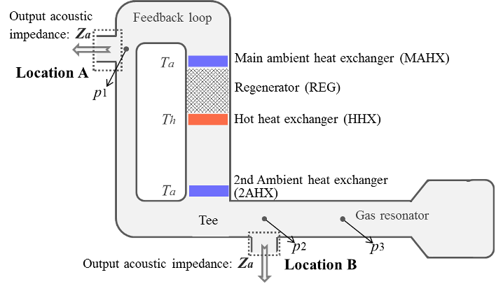
Figure 2. Two output locations of traveling-wave thermoacoustic engines 
Table 1. Main geometric dimensions of traveling-wave thermoacoustic engine. 
Figure 8. Input acoustic power and output electric power vs. operating frequency. 
Figure 7. Equivalent displacements |x1| at (a) location A and (b) location B with respect to output acoustic impedance Za. 
Figure 13. Effect of load resistance on acoustoelectric efficiency of linear alternators. 
Table 2. Parameters of linear alternators. 
Figure 3. Schematic of linear alternators. The coils of the two linear alternators are connected in series with an electric capacitance Ce and a variable load resistance Rl. 
Figure 12. Effect of load resistance on input acoustic impedance of linear alternators. 
Figure 18. Operating frequency and pressure amplitude when linear alternators are connected at location B. 
Figure 11. Effect of electric capacitance on acoustoelectric efficiency of linear alternators. 
Figure 10. Effect of electric capacitance on input acoustic impedance of linear alternators. 
Figure 4. Operating frequency of traveling-wave thermoacoustic engine at (a) location A and (b) location B with respect to output acoustic impedance Za. 
Figure 19. Displacement and electric current when linear alternators are connected at location B. 
Figure 20. Output electric power when linear alternators are connected at location B. 
Figure 16. Displacement and electric current when linear alternators are connected at location A. 
Figure 17. Output electric power and thermal-to-electric efficiency when linear alternators are connected at location A. 
Figure 9. Input acoustic impedances vs. operating frequency. 
Figure 5. Output acoustic powers Wa of traveling-wave thermoacoustic engine at (a) location A and (b) location B with respect to output acoustic impedance Za. 
Figure 6. Thermoacoustic efficiencies ηt-a of traveling-wave thermoacoustic engine at (a) location A and (b) location B with respect to output acoustic impedance Za. 
Figure 21. Thermal-to-electric efficiency when linear alternators are connected at location A. 
Figure 1. Procedure of impedance matching of thermoacoustic electric generator.


Citations
53 citations
51 citations
38 citations
34 citations
Cites background from "Acoustic matching of a traveling-wa..."
...49 Many efforts were recently devoted into employing the engine for power generation by using linear alternators 50 [19-25]....
[...]
...It indicates that the middle coupling position is a low acoustic impedance region, which also requires 190 a low load acoustic impedance for better output performances [19]....
[...]
...Previous work on thermoacoustic-linear alternator coupled systems 72 showed that the acoustic matching between them is critical for the overall performance [19]....
[...]
23 citations
References
39 citations
39 citations
"Acoustic matching of a traveling-wa..." refers background in this paper
...Figure 2 illustrates the schematic of the traveling-wave thermoacoustic engine [17]....
[...]
...[16, 17] were also engaged into the developments of 53 traveling-wave thermoacoustic electric generators recently....
[...]
...5% thermal-to-electric efficiency 58 [17]....
[...]
37 citations
"Acoustic matching of a traveling-wa..." refers methods in this paper
...Several 74 researchers [23-27] used the equivalent circuit method to obtain the equivalent acoustic 75 impedances of the acoustoelectric transducers, and then coupled it with standing-wave 76 thermoacoustic systems....
[...]
36 citations
"Acoustic matching of a traveling-wa..." refers background in this paper
...[28] studied the impedance match for Stirling 80 type cryocoolers....
[...]
35 citations
"Acoustic matching of a traveling-wa..." refers background in this paper
...It 32 is typically composed of a traveling-wave thermoacoustic engine [1-7] or several 33 traveling-wave thermoacoustic conversion units [8, 9] that consist of a hot heat exchanger, a 34 regenerator and a cold heat exchanger, and several linear alternators....
[...]