scispace - formally typeset
Search or ask a question
Proceedings ArticleDOI

Analytical Approaches to the Description of Optical Microresonator Devices

15 Jun 2004-Vol. 709, Iss: 1, pp 48-71
TL;DR: In this paper, a survey of bend mode properties and a coupler description in terms of coupled mode theory is presented for optical ring resonators with square or rectangular cavity shapes, in contrast to the traveling waves found in the microrings.
Abstract: Optical ring resonators are commonly discussed on the basis of a frequency‐domain model, that divides a resonator into coupler elements, ring cavity segments, and the straight port waveguides. We look at the assumptions underlying this model and at its implications, including remarks on reciprocity/symmetry arguments, the general power transfer characteristics, the resonance condition, the spectral distance and width of the resonances, the quantities that describe the resonator performance, and a few remarks about tuning. A survey of bend mode properties and a coupler description in terms of coupled mode theory fills the abstract notions of the model. As an example for devices that rely on a standing wave principle, in contrast to the traveling waves found in the microrings, we consider in less detail microresonators with square or rectangular cavity shapes. Also here a frequency domain coupled mode theory can be applied that opens up simple possibilities to characterize resonant configurations.

Summary (2 min read)

Introduction

  • A key risk for hydrocarbon exploration in southern Libya is source rock presence.
  • This is based on the assumption that U is not able to migrate as a result of weathering processes during rock exposure at the surface, an assumption that has been the subject of some debate (e.g., Chabaux et al. 2003).
  • Therefore, a radioactive peak on the gamma-ray log may also be caused by elevated Th and K contents but may be unrelated to U.

Geological setting

  • The present study focuses on Jabal Eghei, on the western margin of basin.
  • The oldest studied succession, the Hawaz Formation, composed of a cross-bedded and a Skolithos-burrowed sandstone facies association, occupies the westernmost part of the study area, although isolated outcrops have also been found near the eastern margin of the area.
  • The complete thickness of the Hawaz Formation is unknown, but may exceed 100 m (Fig. 2).
  • Hand-held gamma-ray measurements enable understanding of the Tanezzuft Formation to be refined by dividing it into three members.

Material and methods

  • A portable hand-held gamma-ray spectrometer from GF Instruments (formerly Geofyzika, Brno) was used during fieldwork in November‒December 2008 to determine the in situ concentration of radioactive K, U and Th on outcrop exposures.
  • The localities where measurements were performed are shown in Figure 1.
  • To deduce the mineralogical composition of the Tanezzuft Formation sediments, X-ray diffraction (XRD) analyses were performed on three representative samples.
  • The machine operating conditions were set at 35 kV, 40 mA utilising automatic slits and a step size of 0.02º.
  • The samples were prepared as randomly oriented powder samples to which an internal standard of 25% by weight of corundum was added.

Results

  • In total, 179 in situ measurements of K, U and Th were performed covering outcrop exposures of the Hawaz, Mamuniyat and Tanezzuft Formations and of the Mesozoic sandstone.
  • In the following sections, the data are discussed to discriminate (i) between sandstones and mudrock, (ii) between sandstones from different formations, and (iii) between different members of the Tanezzuft Formation.
  • Hawaz Formation and Mamuniyat Formation sandstones and the Mesozoic sandstone show a similar range for Th and U contents, with 2 to 10 ppm for Th and 1 to 3.5 ppm for U. Tanezzuft Formation discrimination Hand-held gamma-ray measurements of the Tanezzuft Formation indicate differences in K content between the three members (Fig. 8).
  • The majority of the samples from the lower member have Th/K values >28, those from the middle member range from 3.5‒12, whilst samples from the upper member have Th/K values between 12 and 28 (Fig. 8E).

Discussion

  • Origins of the gamma-ray signal Before interpreting the observed K, U and Th values, it is useful to discuss the primary factors controlling the K, U and Th signals and the secondary parameters which modify these values during weathering and diagenesis.
  • The commonly observed close relationship between U and TOC contents (Stocks and Lawrence 1990; Lüning and Kolonic 2003) is based on the fact that in seawater U6+ is carried in solution as uranyl carbonate complexes which 'precipitate' under oxygen-depleted, strongly reducing conditions within the sediment during deposition (Wignall and Myers 1988; Klinkhammer and Palmer 1991).
  • Ratios of Th/K enable identification of the dominant mineral type (Fig. 8F), with increasing Th/K values from glauconite → muscovite → illite → mixed-layer clays (illite–smectite) → kaolinite → chlorite → bauxite (Bateman 1985).
  • The upper member of the Tanezzuft Formation (Figs. 3 and 9), containing the graptolite-bearing bed and kaolinite-rich succession, was likely deposited during greenhouse conditions (warm and at least seasonally humid climate) (Fig. 10).

Conclusions

  • Hand-held gamma-ray measurements in outcrop at Jabal Eghei reveal distinct K, U and Th contents for sandstones and mudrocks, which reflect the different mineralogical composition of these strata.
  • Mudrocks show higher values of K, U and Th because they are enriched in clay minerals.
  • Kaolinite presence probably suggests a relatively humid and warm climate during deposition, if recycling of kaolinite from older successions is excluded.
  • The present study clearly shows the applicability of hand-held gamma-ray measurements for chemostratigraphy even in heavily weathered sections in the Libyan Sahara.

Did you find this useful? Give us your feedback

Figures (14)

Content maybe subject to copyright    Report

Analytical Approaches to the Description of
Optical Microresonator Devices
Manfred Hammer, Kirankumar R. Hiremath and Remco Stoffer
MESA
+
Research Institute, University of Twente, The Netherlands
Abstract. Optical ring resonators are commonly discussed on the basis of a frequency-domain
model, that divides a resonator into coupler elements, ring cavity segments, and the straight port
waveguides. We look at the assumptions underlying this model and at its implications, including
remarks on reciprocity/symmetry arguments, the general power transfer characteristics, the reso-
nance condition, the spectral distance and width of the resonances, the quantities that describe the
resonator performance, and a few remarks about tuning. A survey of bend mode properties and
a coupler description in terms of coupled mode theory fills the abstract notions of the model. As
an example for devices that rely on a standing wave principle, in contrast to the traveling waves
found in the microrings, we consider in less detail microresonators with square or rectangular cav-
ity shapes. Also here a frequency domain coupled mode theory can be applied that opens up simple
possibilities to characterize resonant configurations.
1. INTRODUCTION
The current research on microresonators as building blocks for large scale integrated
optics [1] concentrates for a major part on devices with circular, ring- or disk-shaped
cavities. During our participation in the project NAIS [2] we experienced that most ex-
perimental and theoretical discussions of optical microring resonators use notions de-
rived from a quite intuitive frequency domain model. In Section 2 we try to clarify the
assumptions that this “standard” model is based upon, and develop its implications. The
reasoning follows more or less Refs. [3, 4], where we concretize the abstract parame-
terized expressions by a few characteristic (2D) examples for bend modes and coupler
structures, seen as parts of the microresonator. The present model leads to a description
of the interaction between the cavity and the straight waveguides in terms of a frequency
domain coupled mode theory. Alternatively one can adopt a time domain viewpoint,
where the resonance frequencies of an isolated cavity can be directly identified. See Ref.
[5] for a discussion of these concepts.
While the interest in optical ring resonators dates back some time already [6], other
resonator shapes have attracted attention only quite recently. The list includes elliptical
[7, 8], rectangular [9, 10], as well as other, more irregular cavity shapes [11, 12]. The
rectangular variants are the subject of Section 3. In contrast to the microrings, where
traveling waves establish the resonances and where reflections do usually not play a
role, the rectangular resonators are based on a standing wave principle; reflections are
essential for the operation (see e.g. Ref. [9] for details on these notions). Also here
the basics of the device characteristics can be evaluated along a quite general, analytic
frequency domain model [13], though not as explicit as in the case of the microrings.
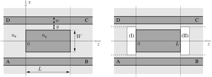
Examples of a bimodal resonance in a rectangular cavity and of the corresponding
multimode facet illustrate these concepts.

z
L/2
L/2
0
D C
BA
R
0
(II)
D C
a b
(I)
A B
d c
FIGURE 1. Schematic ring resonator representation (left) and the split configuration (right): Two
identical directional couplers (I), (II) are connected by cavity waveguide segments of length L/2. Letters
A–D and a–d denote the coupler ports. The entire device has a twofold symmetry with respect to the
centered horizontal and vertical planes. This implies that the four port waveguide segments are identical.
2. “STANDARD MODEL FOR OPTICAL RING RESONATORS
Consider a ring resonator configuration as sketched in Figure 1. Two straight bus or port
waveguides are evanescently coupled to the central cavity ring. If chiefly guided waves
with reasonable confinement are present, one can expect that the interaction between
the cavity and the port cores is localized around the two regions of closest approach.
Hence, for purposes of modeling, the device is divided into these two coupler regions
on the one hand, and the two parts of the cavity loop on the other hand. A prediction of
the power transfer through the resonator requires a description of the light propagation
along the two bent cavity waveguides segments, a model for what happens inside the
coupler regions, and finally a framework to connect the parts. With some generality
one can supply expressions with a few free parameters for the former two ingredients.
Section 2.1 shows how the essentials of the ring resonator power transfer characteristic
are evaluated within this parameterized model. The free parameters are eliminated in
the subsequent paragraphs: Section 2.2 illustrates the basic modal properties of bend
waveguides, Section 2.3 supplies an ansatz for the description of the coupler regions
in terms of coupled mode theory (see Ref. [14] for further details on that subject). For
simplicity, Sections 2.2–2.3 are restricted to two spatial dimensions.
2.1. Abstract resonator model
The “standard” model covers the propagation of light at fixed angular frequency
ω
= kc,
usually specified by the vacuum wavelength
λ
, vacuum wavenumber k = 2
π
/
λ
, and
vacuum speed of light c. All optical fields vary in time according to exp(i
ω
t). The list
of underlying assumptions and approximations includes the following items:
Single polarization operation is considered, none of the waveguide segments and
coupler elements couples waves of different polarization; all waveguides are uni-
modal per polarization orientation.

The elements are purely linear and nonmagnetic. The various kinds of attenuation
for light propagation along the cavity loops are incorporated in the modal proper-
ties, i.e. in the attenuation constant, of the cavity channel.
Backreflections are negligible, inside the couplers as well as in the cavity loops.
Adiabatic” transitions along the light paths are required for the model to be valid.
The interaction between the light paths is negligible outside the coupler regions.
This assumption is likely to become violated by the long outer tails of bend or
gallery modes in small, radiative cavities (see Section 2.2).
We now refer to the schematic splitting of the resonator as introduced in Figure 1. Vari-
ables A
±
, B
±
, C
±
, D
±
(external connections) and a
±
, b
±
, c
±
, d
±
(cavity connections)
denote the amplitudes of the guided modes in the coupler port planes that are identified
by the corresponding letters, where signs ± identify waves that travel in the positive and
negative z-direction. The operation of coupler I can be described by a scattering matrix
that establishes a linear relation between the amplitudes A
, a
, B
+
, b
+
of the outgoing
waves and the amplitudes A
+
, a
+
, B
, b
of the incoming fields,
A
a
B
+
b
+
=
0 0
ρ κ
0 0
χ τ
ρ χ
0 0
κ τ
0 0
A
+
a
+
B
b
, (1)
where the zeros implement the assumption of negligible backreflections. This matrix
is symmetric due reciprocity arguments [15]. The reasoning involves basically an inte-
gration of a “reciprocity identity”, valid for solutions of Maxwell’s equations, over the
coupler domain. Remaining boundary terms establish the symmetry relations between
the field amplitudes on the input- and output ports of the circuit. The precise definition
of the “ports” is crucial for the argument. Independent ports can be realized either by
modal orthogonality (modes of differing order, or guided fields and surrounding radia-
tion) or by spatially well separated outlets. The theorem holds for linear, nonmagnetic,
potentially attenuating materials, in the presence of radiative losses, and irrespectively
of the particular shape of the connecting cores. See Ref. [15] for details.
Due to the additional symmetry of the coupler element with respect to the vertical
plane z = 0 one can expect the transmission A
+
b
+
to be equal to the transmission
B
a
. With a symmetric placement of the port planes and for identical mode profiles
used for incident and outgoing waves, the corresponding entries
κ
(lower left corner) and
χ
(second row, third column) of the scattering matrix in Eq. (1) must coincide
κ
=
χ
[15]. Coupler I transforms the mode amplitudes according to
A
a
=
ρ κ
κ τ
B
b
and
B
+
b
+
=
ρ κ
κ τ
A
+
a
+
. (2)
An analogous expression applies to coupler II, if the elements are identical:
D
d
=
ρ κ
κ τ
C
c
and
C
+
c
+
=
ρ κ
κ τ
D
+
d
+
. (3)

(The approximate constraint of lossless couplers requires |
ρ
|
2
+ |
κ
|
2
= 1 and |
κ
|
2
+
|
τ
|
2
= 1, consequently |
ρ
|
2
= |
τ
|
2
= 1 |
κ
|
2
. Provided the input- and output planes
are placed properly, one can even restrict to
ρ
=
τ
. Note that these properties are not
exploited in the following reasoning.)
Suppose the single mode ring waveguide segments of length L/2 support the relevant
cavity mode with complex propagation constant
γ
=
β
i
α
, for phase propagation
constant
β
(real, positive) and attenuation constant
α
(real, positive, power attenuation
constant: 2
α
). For propagation along the cavity loop with s measuring the propagation
distance, the fields evolve according to exp(i
γ
s), leading to the relations
c
= b
+
exp(i
β
L/2) exp(
α
L/2), a
+
= d
exp(i
β
L/2) exp(
α
L/2), and
b
= c
+
exp(i
β
L/2) exp(
α
L/2), d
+
= a
exp(i
β
L/2) exp(
α
L/2)
(4)
of the mode amplitudes in the cavity port planes of the couplers.
2.1.1. Power transfer
Due to the linearity and the symmetry of the device it is sufficient to consider an
excitation in only one of the external ports, say in port A. Given input amplitudes
A
+
=
P
in
, B
= D
+
= C
= 0, Eqs. (2)–(4) are to be solved for the directly transmitted
power P
T
= |B
+
|
2
, and for the backwards dropped power P
D
= |D
|
2
, where neglecting
reflections implies that there is no backreflected power A
= 0 and no power dropped in
the forward direction C
+
= 0. This leads to the expressions
D
=
κ
2
p
1
τ
2
p
2
A
+
, B
+
=
ρ
+
κ
2
τ
p
2
1
τ
2
p
2
A
+
, (5)
for the amplitudes in the drop- and through-port, where p = exp(i
β
L/2) exp(
α
L/2).
Splitting the cavity transfer coefficient
τ
of the coupler matrix as
τ
= |
τ
|exp(i
ϕ
), and
using the abbreviation
τ
κ
2
/
ρ
= d exp(i
ψ
), for real d and
ψ
, one can write expressions
P
D
= P
in
|
κ
|
4
exp(
α
L)
1 + |
τ
|
4
exp(2
α
L) 2|
τ
|
2
exp(
α
L) cos(
β
L 2
ϕ
)
(6)
for the dropped optical power and
P
T
= P
in
|
ρ
|
2
(1 + |
τ
|
2
d
2
exp(2
α
L) 2|
τ
|d exp(
α
L) cos(
β
L
ϕ
ψ
))
1 + |
τ
|
4
exp(2
α
L) 2|
τ
|
2
exp(
α
L) cos(
β
L 2
ϕ
)
(7)
for the directly transmitted power. Note that here L is the length of those parts of the
cavity that are not already covered by the coupler model. In case of a ring with radius
R, where each coupler region includes an arc length l =
θ
R of the cavity, one should
evaluate the above expressions with L = 2
π
R2
θ
R (though one frequently encounters
the approximation L = 2
π
R corresponding to an interaction length that is short when
compared to the cavity ring). Figure 2 shows a typical resonator spectrum as predicted
by these expressions. Its features will be discussed in the following sections.

1546.2 1546.4 1546.6 1546.8 1547 1547.2 1547.4
0
0.2
0.4
0.6
0.8
1
λ [nm]
P
D
, P
T
2δλ
P
D
P
T
1540 1545 1550 1555 1560
0
0.2
0.4
0.6
0.8
1
λ [nm]
P
D
, P
T
P
D
P
T
∆λ
FIGURE 2. Wavelength dependence of the relative dropped and transmitted power fractions P
D
and P
T
,
for a 2D ring resonator with cavity segments according to Figure 4 and coupler regions as specified in
Figure 7, for a cavity radius R = 50
µ
m, a gap g = 0.9
µ
m, and for TE polarized light. Characterizing
quantities are the free spectral range
λ
= 5.01 nm, the resonance width 2
δ λ
= 0.17 nm, a finesse of
F = 30, the quality factor Q = 9400, and the power drop at resonance of 0.44.
2.1.2. Spectral response & resonances
Almost all quantities that enter expressions (5), (6), (7) must be assumed to be wave-
length dependent. Hence the proper way to compute the resonator spectrum would be to
evaluate the properties of the port waveguides, the cavity segments, and of the coupler
regions as input for the above expressions, for a series of wavelengths.
A little more insight can be gained if one accepts the following approximation: If only
a narrow wavelength interval needs to be considered, one can assume that the significant
changes in P
D
and P
T
originate exclusively from the cosine terms that include the
phase information. To account (approximately) for a nonnegligible length l of the cavity
segments in the coupler regions, we rewrite the phase term as
β
L2
ϕ
=
β
L
cav
φ
, with
L
cav
being the complete cavity length, and
φ
= 2
β
l + 2
ϕ
(a corresponding procedure is
applied to the phase term in the numerator of Eq. (7)). Further only the wavelength
dependence of the phase propagation constant
β
as it appears explicitly in the term
β
L
cav
φ
is considered. In this way we incorporate the wavelength dependence of the
phase gain
β
L
cav
along the entire cavity, but disregard the wavelength dependence of the
phase change
φ
that is introduced by the interaction with the port waveguides.
Resonances, maxima of the dropped power, are now characterized by singularities in
the denominators of Eqs. (6), (7), i.e. by the condition cos(
β
L
cav
φ
) = 1, or alterna-
tively by the constraint
β
=
2m
π
+
φ
L
cav
=:
β
m
for integer m. (8)
In case a resonant configuration is realized, the dropped power evaluates to
P
D
|
β
=
β
m
= P
in
|
κ
|
4
exp(
α
L)
(1 |
τ
|
2
exp(
α
L))
2
. (9)
Properly computed values for
κ
and
τ
include already the losses along the parts of the
cavity inside the couplers. Therefore L in Eq. (9) (and in those places of Eqs. (6), (7)

Citations
More filters
Book
01 Jan 2006
TL;DR: Theorems and Formulas used in this chapter relate to theorems in optical waveguides and lightwave Circuits that describe the behaviour of Planar Waveguides through the response of the E-modulus effect.
Abstract: Preface 1. Wave Theory of Optical Waveguides 2. Planar Optical Waveguides 3. Optical Fibers 4. Couple Mode Theory 5. Nonlinear Optical Effects in Optical Fibers 6. Finite Element Method 7. Beam Propagation Method 8. Staircase Concatention Method 9. Planar Lightwave Circuits 10. Theorems and Formulas Appendix

359 citations

Journal ArticleDOI
TL;DR: In this article, a rigorous classical analytic frequency domain model of con?ned optical wave propagation along 2D bent slab waveguides and curved dielectric interfaces is investigated, based on a piecewise ansatz for bend mode profiles in terms of Bessel and Hankel functions.
Abstract: A rigorous classical analytic frequency domain model of con?ned optical wave propagation along 2D bent slab waveguides and curved dielectric interfaces is investigated, based on a piecewise ansatz for bend mode profiles in terms of Bessel and Hankel functions This approach provides a clear picture of the behaviour of bend modes, concerning their decay for large radial arguments or effects of varying bend radius Fast and accurate routines are required to evaluate Bessel functions with large complex orders and large arguments Our implementation enabled detailed studies of bent waveguide properties, including higher order bend modes and whispering gallery modes, their interference patterns, and issues related to bend mode normalization and orthogonality properties

95 citations

01 Jan 2006
TL;DR: In this article, an international forum for original research papers, tutorial reviews and letters in optical physics, optical engineering and optoelectronics, including solid state and gas lasers, optical communication systems, fibres and planar waveguides, nonlinear optics, ultra-fast phenomena, optical storage, photonic switching and more.
Abstract: ▶ An international forum for original research papers, tutorial reviews and letters in optical physics, optical engineering and optoelectronics ▶ Coverage includes solid state and gas lasers, optical communication systems, fibres and planar waveguides, non-linear optics, ultra-fast phenomena, optical storage, photonic switching and more ▶ Special issues focus on topics of current interest ▶ 100% of authors who answered a survey reported that they would definitely publish or probably publish in the journal again

51 citations

Journal ArticleDOI
TL;DR: High optical quantum efficiency (90%) resonant-cavity-enhanced mid-infrared photodetectors fabricated monolithically on a silicon platform are demonstrated, promising for monolithic integration with Si readout integrated circuits.
Abstract: In this paper, we demonstrate high optical quantum efficiency (90%) resonant-cavity-enhanced mid-infrared photodetectors fabricated monolithically on a silicon platform. High quality photoconductive polycrystalline PbTe film is thermally evaporated, oxygen-sensitized at room temperature and acts as the infrared absorber. The cavity-enhanced detector operates in the critical coupling regime and shows a peak responsivity of 100 V/W at the resonant wavelength of 3.5 microm, 13.4 times higher compared to blanket PbTe film of the same thickness. Detectivity as high as 0.72 x 10(9) cmHz(1/2)W(-1) has been measured, comparable with commercial polycrystalline mid-infrared photodetectors. As low temperature processing (< 160 degrees C) is implemented in the entire fabrication process, our detector is promising for monolithic integration with Si readout integrated circuits.

47 citations

Journal ArticleDOI
TL;DR: In this article, a spatially three-dimensional (3-D), fully vectorial coupled mode theory model for the interaction between several straight or bent dielectric optical waveguides, each supporting multiple modes, is described.

43 citations


Cites background from "Analytical Approaches to the Descri..."

  • ...[19, 31] can be applied, that predict a symmetric scattering matrix....

    [...]

References
More filters
Book
01 Jan 2000

1,493 citations

Book
01 Jan 2006
TL;DR: Theorems and Formulas used in this chapter relate to theorems in optical waveguides and lightwave Circuits that describe the behaviour of Planar Waveguides through the response of the E-modulus effect.
Abstract: Preface 1. Wave Theory of Optical Waveguides 2. Planar Optical Waveguides 3. Optical Fibers 4. Couple Mode Theory 5. Nonlinear Optical Effects in Optical Fibers 6. Finite Element Method 7. Beam Propagation Method 8. Staircase Concatention Method 9. Planar Lightwave Circuits 10. Theorems and Formulas Appendix

359 citations

Book
31 Oct 1991
TL;DR: In this article, the weak guidance approximation of waveguides embedded in a low-index medium is described, where the waveguide can be interpreted as an anisotropic waveguide.
Abstract: 1. Basic Concepts. Maxwell equations. Normal mode theory. Scattering matrices. Coupled mode theory. Variational techniques. 2. Modes of Optical Waveguides - I. The weak guidance approximation. Waveguides embedded in a low index medium. Step-index slab waveguides. Step-index circular fibers. Weakly guiding anisotropic waveguides. 3. Modes of Optical Waveguides - II. Graded slabs or fibers. 3-D planar waveguides. Numerical methods for arbitrary cross-sections. Leaky modes. 4. Perturbation Techniques. Modal expansion method. Variational techniques. Reciprocity techniques. Global perturbation methods. Applications. 5. Non-Uniform Systems. Local mode expansions. Bent waveguides. Bent and twisted waveguides. Non-uniform curvatures. 6. Discontinuities. Excitation of a guided mode through a junction. Abrupt discontinuities. Bibliography. Index.

272 citations

Journal ArticleDOI
TL;DR: In this paper, the theory of dielectric optical waveguides has been studied in the context of optical waveguide design and its application in the field of optical fiber optics.
Abstract: (1992). Theory of Dielectric Optical Waveguides. 2nd Edition. Journal of Modern Optics: Vol. 39, No. 4, pp. 901-901.

127 citations


"Analytical Approaches to the Descri..." refers background in this paper

  • ...Manifold variants of coupled mode theory have been proposed, for a variety of different domains of applications [19, 15, 20, 4]....

    [...]

Proceedings ArticleDOI
15 Jun 2004
TL;DR: In this paper, optical microresonators are presented as promising basic building blocks for filtering, amplification, modulation, switching and sensing active functions can be obtained by monolithic integration or a hybrid approach using materials with thermo-, electro-, and opto-optic properties and materials with optical gain.
Abstract: In the last years much effort has been taken to arrive at optical integrated circuits with high complexity and advanced functionality For this aim high index contrast structures are employed resulting in photonic wires in conventional index guiding waveguides or in photonic bandgap structures In both cases the number of functional elements within a given chip area can be enhanced by several orders of magnitude: VLSI photonics In this talk optical microresonators are presented as promising basic building blocks for filtering, amplification, modulation, switching and sensing Active functions can be obtained by monolithic integration or a hybrid approach using materials with thermo‐, electro‐ and opto‐optic properties and materials with optical gain Examples are mainly taken from work at MESA+

60 citations

Frequently Asked Questions (11)
Q1. What contributions have the authors mentioned in the paper "Analytical approaches to the description of optical microresonator devices" ?

The authors look at the assumptions underlying this model and at its implications, including remarks on reciprocity/symmetry arguments, the general power transfer characteristics, the resonance condition, the spectral distance and width of the resonances, the quantities that describe the resonator performance, and a few remarks about tuning. As an example for devices that rely on a standing wave principle, in contrast to the traveling waves found in the microrings, the authors consider in less detail microresonators with square or rectangular cavity shapes. 

Disregarding its influence on the performance of the (short) couplers as a first approximation, a tuning mechanism, modeled by a small parameter p, affects mainly the light propagation along the cavity ring. 

The two facets at the ends of the cavity segment cause strong reflections of the waves that are excited inside the cavity, while one can assume that they have much less influence on the waves that travel along the port cores. 

As expected, in general the net power transfer between the straight and the bend core grows with decreasing gap width, i.e. with increasing interaction strength, and with increasing bend radius, i.e. with increasing interaction length. 

(3)(The approximate constraint of lossless couplers requires |ρ|2 + |κ|2 = 1 and |κ|2 + |τ|2 = 1, consequently |ρ|2 = |τ|2 = 1 − |κ|2. Provided the input- and output planes are placed properly, one can even restrict to ρ = τ . 

According to the former quantitative characterization in terms of amplification factors based on eigenvalues of Ω, high quality resonances in a dielectric rectangle require a facet reflectivity close to unity for the contributing cavity modes. 

While this refers to a single mode resonance with a field based upon only one (forward and backward propagating) mode per axis, a bimodal resonance is characterized by the existence of a pair of modes per axis orientation that satisfy the phase relations simultaneously. 

Due to the additional symmetry of the coupler element with respect to the vertical plane z = 0 one can expect the transmission A+ → b+ to be equal to the transmission B− → a−. 

If additionally the radius of the bent core is increased (bottom), one arrives at a configuration with a coupling coefficient |κ|2 that is almost equal to the one of the structure at the top, i.e. the couplers effect similar levels of power transfer between the straight and the bend waveguide, despite the fact that the strength as well as the length of the interaction is much larger in the bottom configuration with larger bend radius andsmaller gap width. 

Hence the proper way to compute the resonator spectrum would be to evaluate the properties of the port waveguides, the cavity segments, and of the coupler regions as input for the above expressions, for a series of wavelengths. 

R (though one frequently encounters the approximation L = 2πR corresponding to an interaction length that is short when compared to the cavity ring).