scispace - formally typeset
Search or ask a question
Journal ArticleDOI

Characteristics of sound propagation in shallow water over an elastic seabed with a thin cap-rock layer.

11 Jul 2013-Journal of the Acoustical Society of America (Acoustical Society of America)-Vol. 134, Iss: 1, pp 207-215
TL;DR: Low-frequency transmission loss data collected from an offshore seismic survey in Bass Strait on the southern Australian continental shelf are analyzed and shown to be in broad agreement with the numerical predictions based on the theoretical analysis and modeling using an elastic parabolic equation solution for range-dependent bathymetry.
Abstract: Measurements of low-frequency sound propagation over the areas of the Australian continental shelf, where the bottom sediments consist primarily of calcarenite, have revealed that acoustic transmission losses are generally much higher than those observed over other continental shelves and remain relatively low only in a few narrow frequency bands. This paper considers this phenomenon and provides a physical interpretation in terms of normal modes in shallow water over a layered elastic seabed with a shear wave speed comparable to but lower than the water-column sound speed. A theoretical analysis and numerical modeling show that, in such environments, low attenuation of underwater sound is expected only in narrow frequency bands just above the modal critical frequencies which in turn are governed primarily by the water depth and compressional wave speed in the seabed. In addition, the effect of a thin layer of harder cap-rock overlaying less consolidated sediments is considered. Low-frequency transmission loss data collected from an offshore seismic survey in Bass Strait on the southern Australian continental shelf are analyzed and shown to be in broad agreement with the numerical predictions based on the theoretical analysis and modeling using an elastic parabolic equation solution for range-dependent bathymetry.

Summary (2 min read)

Introduction

  • In addition, the effect of a thin layer of harder cap-rock overlaying less consolidated sediments is considered.
  • In such conditions, the effect of shear in the seabed can have a substantial effect on acoustic propagation in the overlying water column.
  • They a)Author to whom correspondence should be addressed.

II. NUMERICAL MODELING OF LOW-FREQUENCY SOUND PROPAGATION

  • The numerical predictions made in this section are based on the formulation given in Ellis and Chapman (1985) and the Wave Number Integration (WNI) transmission loss calculation method implemented in computer programs SCOOTER and FIELDS (Porter, 2007).
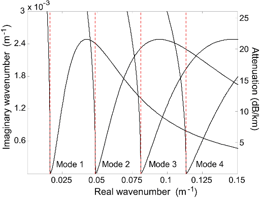
  • The natural logarithm transformation of Eq. (2) gives 2cmH u ilnðjRjÞ ¼ pð2m 1Þ; (3) where u is the phase of the reflection coefficient.
  • At its critical frequency and below, a mode is radiating into the seabed, and its contribution to the sound intensity in the far field in the water column is minor.
  • The result is that the minimum transmission loss for a given mode occurs at a frequency slightly higher than the modal critical frequency.
  • If the wavelength remains much larger than the top layer thickness, then the major effect of the cap rock is a rapid reduction of the reflection coefficient at the basement critical angle as the frequency increases (Fig. 5).

A. Experimental measurements

  • Measurements of the transmission loss of airgun signals from an offshore seismic exploration survey were made in 2011 in the western part of Bass Strait as part of an 8-month sea noise monitoring and blue whale tracking program supported by Origin Energy.
  • The easternmost inshore and offshore transects are shown in Fig.
  • This result was obtained from the best fit to the ESD values of the airgun signals recorded by receivers 1 and 3.
  • For the mean sea depth of approximately 115 m along the acoustic paths from the inshore seismic transect to the receiver array and the mean sound speed in water of 1509 m/s, the compressional wave speed derived from the critical frequencies of modes 1 and 2 at approximately 5 and 14 Hz, respectively, is expected to be within 2000–2100 m/s.
  • The frequency band of the maximum intensity of mode 3 at about 24 Hz was accurately predicted by both numerical models; however, the range-independent scenario modeled by WNI resulted in noticeably lower transmission loss around the critical frequency of mode 3, while the PE method applied to the range-dependent bathymetry resulted in an accurate prediction of the transmission loss.

IV. CONCLUSIONS

  • Low-frequency acoustic propagation over elastic seabeds with shear wave speeds less than the water column sound speed is characterized by relatively low transmission loss only in narrow frequency bands.
  • Each of these bands occurs just above the critical frequency of a mode and is a result of two counteracting factors:.
  • Moreover, the numerical model predicted that the group velocity should gradually decrease with increasing mode number, which was not observed in the experimental data.
  • Understanding the propagation of low-frequency underwater sound over continental shelf seabeds is very important to the prediction of sound levels from all low-frequency sources but particularly for the prediction of levels due to offshore seismic surveys.
  • These surveys utilize arrays of airguns that have source spectra similar to that shown in Fig. 10 and produce large amounts of low-frequency acoustic energy.

Did you find this useful? Give us your feedback

Figures (14)

Content maybe subject to copyright    Report

Characteristics of sound propagation in shallow water over an
elastic seabed with a thin cap-rock layer
Alec J. Duncan,
a)
Alexander N. Gavrilov, Robert D. McCauley, and Iain M. Parnum
Centre for Marine Science and Technology, Curtin University, G.P.O. Box U1987, Perth, Western Australia
6845, Australia.
Jon M. Collis
Colorado School of Mines, 1500 Illinois Street, Golden, Colorado 80401
(Received 31 August 2012; revised 15 March 2013; accepted 7 May 2013)
Measurements of low-frequency sound propagation over the areas of the Australian continental
shelf, where the bottom sediments consist primarily of calcarenite, have revealed that acoustic
transmission losses are generally much higher than those observed over other continental shelves
and remain relatively low only in a few narrow frequency bands. This paper considers this phenom-
enon and provides a physical interpretation in terms of normal modes in shallow water over a lay-
ered elastic seabed with a shear wave speed comparable to but lower than the water-column sound
speed. A theoretical analysis and numerical modeling show that, in such environments, low attenua-
tion of underwater sound is expected only in narrow frequency bands just above the modal critical
frequencies which in turn are governed primarily by the water depth and compressional wave speed
in the seabed. In addition, the effect of a thin layer of harder cap-rock overlaying less consolidated
sediments is considered. Low-frequency transmission loss data collected from an offshore seismic
survey in Bass Strait on the southern Australian continental shelf are analyzed and shown to be in
broad agreement with the numerical predictions based on the theoretical analysis and modeling
using an elastic parabolic equation solution for range-dependent bathymetry.
V
C
2013 Acoustical Society of America. [http://dx.doi.org/10.1121/1.4809723]
PACS number(s): 43.30.Ma, 43.30.Bp [NPC] Pages: 207–215
I. INTRODUCTION
Substantial areas of continental shelves around the
world are covered with a layer of relatively soft unconsoli-
dated sediments, such as sand, clay, or silt, in which the
shear modulus is sufficiently low that the acoustic medium
of the sediment can be reasonably well approximated by a
fluid. The additional loss mechanism caused by the shear
waves in the sediment is accounted for by an increase in the
compressional wave attenuation coefficient. Over large areas
of the continental shelves this soft sediment layer is thick
enough that shear waves in the underlying basement can be
ignored when modeling sound propagation in the water col-
umn, leading to all-fluid seabed models. Sound propagation
over fluid seabeds in shallow water has been thoroughly con-
sidered in many publications, from the pioneering work by
Pekeris (1948) to the most recent book on shallow water
acoustics by Katsnelson et al. (2012). However, there are
many places on the world’s continental shelves where the
unconsolidated sediment layer is thin or even absent for vari-
ous reasons, such as low sediment discharge from rivers and
highly dynamic ocean environments, resulting in strong sedi-
ment transport exposing underlying sedimentary rocks. In
such conditions, the effect of shear in the seabed can have a
substantial effect on acoustic propagation in the overlying
water column.
Acoustic reflection from a layered elastic seabed was
analyzed by Brekhovskikh (1960), and Ewing et al. (1957)
considered acoustic propagation in the water column over an
elastic seabed with an emphasis on interface waves. Victor
et al. (1965) theoretically modeled impulsive sound propaga-
tion in a fluid layer overlying a layered solid whereas
Tolstoy and Clay (1966) considered the dispersive character-
istics of normal modes propagating in water over an elastic
basement. Ellis and Chapman (1985) analyzed phase and
group velocities and attenuation of normal modes in shallow
water channels, where the shear wave speed in the seabed
was lower than the sound speed in water. Using an adiabatic
mode approximation, Arvelo and
Uberall (1990) modeled
the influence of elastic waves in the seafloor and varying ba-
thymetry on acoustic transmission loss in shallow water.
However, neither Ellis and Chapman (1985) nor Arvelo and
Uberall (1990) considered the frequency-dependence of low-
frequency sound propagation over an elastic bottom in detail.
Lobanov and Petukhov (1993) used the theoretical deriva-
tions made in Ellis and Chapman (1985) to explain the
space-frequency pattern of the sound field measured from a
broadband acoustic source in shallow water over bedrock,
but only considered the case in which the shear wave speed
was higher than the water column sound speed.
A shallow water environment with a shear wave speed
in the seabed comparable to but smaller than the water col-
umn sound speed is typical for certain areas of continental
shelf where the top layers of the seabed consist of limestone,
a sedimentary rock composed of partly or fully cemented
calcite and aragonite grains. Duncan et al. (2009) modeled
low-frequency sound propagation over calcarenite, which is
a type of soft limestone that makes up the majority of the
western and southern continental shelves of Australia. They
a)
Author to whom correspondence should be addressed. Electronic mail:
a.duncan@cmst.curtin.edu.au
J. Acoust. Soc. Am. 134 (1), July 2013
V
C
2013 Acoustical Society of America 2070001-4966/2013/134(1)/207/9/$30.00
Downloaded 23 Sep 2013 to 134.7.248.132. Redistribution subject to ASA license or copyright; see http://asadl.org/terms

assumed the compressional and shear wave speed in calcar-
enite to be 2800 m/s and 1400 m/s, respectively, and found
that the transmission loss at low frequencies was relatively
low only within narrow frequency bands just above the criti-
cal frequencies of low-order modes, with these frequencies
being governed primarily by the water depth and compres-
sional wave speed in the calcarenite. Chotiros and Isakson
(2010) examined sound propagation in the same environ-
ment, but using a Biot-Stoll poroelastic model of calcarenite,
rather than the elastic model assumed by Duncan et al. Their
numerical prediction did not show the narrow frequency
banding in the transmission loss predicted by the elastic
seabed model; however, their results were inconclusive
because a number of their seabed model parameters were
highly uncertain due to a lack of detailed information about
the properties of the material.
Acousto-elastic properties of limestone vary greatly
depending on its method of formation, composition, and
degree of cementation. In the case of the Australian conti-
nental shelf, the calcarenite was formed when it was exposed
to the atmosphere during past periods of low sea level.
Exposure of calcium-carbonate rich marine sediments to
fresh water from atmospheric precipitation resulted in
the calcium carbonate in the top layer of sediment partly
dissolving, penetrating deeper as a pore fluid and then
re-crystallizing, cementing the remaining sediment grains to-
gether. This process depended on several environmental fac-
tors and was not constant in time. As a result, calcarenite
seabeds assume a layered structure with geoacoustic proper-
ties changing abruptly, and non-monotonically, with depth.
Once re-submerged by rising sea level, wave action and/or
currents often eroded the seabed until a relatively hard layer
was reached. It is therefore common for seabeds of this type
to have a cap of harder rock overlying softer material.
Some peculiarities of low-frequency sound propagation
over calcarenite seabeds are considered in this paper based
on normal mode theory, numerical modeling, and measure-
ments of airgun signals made during a commercial seismic
survey in Bass Strait, Australia, in 2011. In Sec. II, numeri-
cal modeling is used to investigate the narrowband sound fil-
tering and waveguide dispersion properties of a shallow
water acoustic channel over a calcarenite seabed. A simpli-
fied model of the channel is assumed here to analyze in
detail the principal effects of sound propagation over such
seabeds. Variations in modal attenuation and low-frequency
transmission loss due to changes in water depth and/or geoa-
coustic properties of the sediment along the acoustic propa-
gation path are considered. The effect of a thin layer of cap
rock overlaying less cemented calcarenite is also modeled.
This study is focused primarily on the peculiarities of long-
range propagation in the water column, and consequently the
characteristics of evanescent modes propagating along inter-
faces between water and sediment layers are not considered
in detail.
Transmission loss (TL) measurements, conducted over
the continental shelf in Bass Strait are discussed in Sec. III.
The peculiarities of low-frequency sound propagation,
including transmission loss and dispersion, observed in the
experimental measurements are interpreted in Sec. III based
on the numerical modeling results presented in Sec. II and
numerical predictions for range-dependent bathymetry using
an algorithm based on the parabolic approximation (Collis
et al. , 2008).
Potential implications of the observed and modeled
sound propagation effects for predicting sound exposure of
marine environments due to man-made sources of under-
water noise used in offshore operations, such as seismic sur-
veys, are discussed in Sec. IV.
II. NUMERICAL MODELING OF LOW-FREQUENCY
SOUND PROPAGATION
The numerical predictions made in this section are based
on the formulation given in Ellis and Chapman (1985) and
the Wave Number Integration (WNI) transmission loss cal-
culation method implemented in computer programs
SCOOTER and FIELDS (Porter, 2007). The primary acous-
tic channel model used for numerical analysis consists of an
isovelocity (C
w
¼ 1500 m/s) water layer of 110 m depth over
a semi-infinite halfspace of semi-cemented calcarenite with
a compressional wave speed of 2000 m/s, shear wave speed
of 900 m/s and density of 1900 kg/m
3
. The acoustic source
was assumed to be at 7 m below the sea surface and the re-
ceiver was placed on the seafloor. The choice of most of the
modeling parameters was based on the conditions of experi-
mental measurements and some estimates made from the
interpretation of experimental results presented in Sec. III;
however, the compressional and shear wave attenuations in
the seabed were both set to zero in order to more clearly
illustrate the effects of interest. More realistic attenuations
are used in the comparison with experimental data given in
Sec. III.
The transmission loss versus range and frequency calcu-
lated via WNI, and shown in the top panel of Fig. 1, reveals
a series of almost regularly spaced narrow frequency bands
of relatively low transmission loss, contrasting sharply with
the background of high loss at other frequencies. The modu-
lus of the Green’s function shown in the bottom panel of
Fig. 1 demonstrates that the bands of low transmission loss
are located just above the critical frequencies of individual
modes in a Pekeris waveguide having the same seabed com-
pressional sound speed as the elastic bottom:
F
cr
m
¼
ðm 1=2Þ C
w
2Hð1 C
2
w
=C
2
p
Þ
1=2
; (1)
where H is water depth, C
w
is the water column sound speed,
C
p
is the compressional wave speed in the seabed, and m is
the mode number. The Scholte wave propagating along the
water-sediment interface can also be distinguished in the
Green’s function at low frequencies. The Scholte wave does
not have a critical frequency, and its spectrum is governed
by the source and receiver depth. The further the source and/
or receiver are from the interface, the narrower the spectrum
of the Scholte wave will be.
The complex modal wave numbers k
m
can be calculated
from the poles of the Green’s function by finding roots of
Eq. (B5) in Ellis and Chapman (1985):
208 J. Acoust. Soc. Am., Vol. 134, No. 1, July 2013 Duncan et al.: Sound propagation over elastic seabeds with cap-rock
Downloaded 23 Sep 2013 to 134.7.248.132. Redistribution subject to ASA license or copyright; see http://asadl.org/terms

1 þ e
2icH
R ¼ 0; (2)
where c is the vertical component of the wave number in the
water layer and R is the plane-wave reflection coefficient of
the seabed. The natural logarithm transformation of Eq. (2)
gives
2c
m
H u ilnðjR ¼ pð2m 1Þ; (3)
where u is the phase of the reflection coefficient. The term
2pm on the right hand side arises from the 2p ambiguity of
the phase u. Equation (3) is more robust than Eq. (2) with
respect to finding complex roots and is easy to interpret. For
c
m
corresponding to grazing angles where jR1, Eq. (3)
does not contain imaginary components and hence c
m
is also
real. Consequently, the modal horizontal wave numbers are
real for any m satisfying c
m
< x=C
w
. For the case of interest
here (C
s
< C
w
, where C
s
is the shear wave speed in the
seabed), this criterion is met for the water column modes,
but not for the Scholte wave, which can be referred to as
mode 0. Equation (3) is therefore suitable for finding the
water column modes but not appropriate for finding the
Scholte mode. The solution of Eq. (3) for the primary envi-
ronmental model is shown in Fig. 2 for modes 1 to 4. The
reflection coefficient was calculated using the program
BOUNCE by Porter (2007). The imaginary part of the modal
horizontal wave numbers k
m
, and consequently modal
attenuation, are equal to zero only at the corresponding criti-
cal frequency and grow rapidly above it. Hence, the transfer
function of a shallow water acoustic channel over a calcaren-
ite seabed can be considered as a set of narrowband filters at
low frequencies.
In the Pekeris model of sound propagation in shallow
water over a fluid bottom, the transfer function of individual
modes is dominated by higher frequency components well
above the critical frequency, where the modal group velocity
increases with frequency. This results in intra-modal fre-
quency dispersion in which the higher frequency compo-
nents of individual modes propagate faster than the lower
frequency ones. For propagation over a calcarenite seabed
this situation is reversed: As can be seen in Fig. 3, frequency
FIG. 1. (Top) Transmission loss over semi-cemented calcarenite without
bulk acoustic attenuation and (bottom) modulus of Green’s function. The
circles indicate the critical frequencies of modes 1-4 with corresponding
wave numbers.
FIG. 2. (Color online) Imaginary versus real part of the horizontal wave
number for modes 1 to 4 calculated for the primary model of a shallow
water acoustic channel with an elastic seabed. The dashed lines indicate real
wave numbers at the critical frequencies given by Eq. (1). The signal fre-
quency varied from 4 to 40 Hz.
FIG. 3. Group velocities of modes 1–4 versus frequency calculated for the
primary model of a shallow water acoustic channel over calcarenite. Modal
attenuation is gray-scale coded. Values above 0.2 dB/km are shown as a dot-
ted line.
J. Acoust. Soc. Am., Vol. 134, No. 1, July 2013 Duncan et al.: Sound propagation over elastic seabeds with cap-rock 209
Downloaded 23 Sep 2013 to 134.7.248.132. Redistribution subject to ASA license or copyright; see http://asadl.org/terms

components just above the critical frequency dominate the
modal transfer function and have a modal group velocity
that decreases rapidly with increasing frequency.
At its critical frequency and below, a mode is radiating
(leaking) into the seabed, and its contribution to the sound
intensity in the far field in the water column is minor. At fre-
quencies higher than critical, the mode becomes trapped by
the sound channel formed by the water column and seabed.
As the frequency is increased, more of the mode energy is
concentrated in the water column, which would lead to lower
transmission loss. However, this effect is counteracted by
the increase in modal attenuation with increasing frequency
that occurs for frequencies above critical (Fig. 2). The result
is that the minimum transmission loss for a given mode
occurs at a frequency slightly higher than the modal critical
frequency.
The modal critical frequencies shift with changes in the
sea depth and compressional wave speed in the sediment. As
a result, the frequency bands of low transmission loss of
individual modes also change. The sensitivity of these bands
to sea depth variations is illustrated in Fig. 4. The attenuation
coefficient of mode 1 remains relatively small (less than
0.5 dB/km) only within a small range of depth variations of
about 10 m. Attenuation of the higher modes is even more
sensitive to variations in sea depth. Consequently, the trans-
fer function of an individual mode in a range dependent
channel can be represented by a product of transfer functions
of narrowband filters with varying central frequencies. If at
least one of these frequency bands does not overlap with all
others, then attenuation of this mode will be high.
The case of a layered elastic seabed, i.e., one consisting
of sediment layers with distinct geoacoustic properties, is con-
sidered next. Of particular interest is the case of a basement
consisting of relatively soft semi-consolidated sediment over-
lain by a thin (1 m) layer of cap rock. Geoacoustic parameters
assumed for the basement are the same as those of the semi-
cemented calcarenite used in the primary model. The top layer
is assumed to consist of well-cemented calcarenite (limestone)
with a compressional wave speed of 2600 m/s, shear wave
speed of 1200 m/s, and density of 2200 kg/m
3
.
In contrast to the halfspace model of the seabed with
uniform geoacoustic properties assumed in the primary
model, the reflection coefficient from a layered seabed is fre-
quency dependent. At very low frequencies, when the layer
thickness is negligible compared to the acoustic wavelength,
the cap rock is almost transparent to sound waves and hence
the reflection coefficient is governed by the geoacoustic
properties of the basement. However, the effect of the cap
rock layer increases rapidly with frequency. If the wave-
length remains much larger than the top layer thickness, then
the major effect of the cap rock is a rapid reduction of the
reflection coefficient at the basement critical angle as the fre-
quency increases (Fig. 5). As a result, the effect of the imagi-
nary part of Eq. (3) on modal wave numbers increases with
frequency, which leads to a significant increase in modal
attenuation, including at the critical frequencies (Fig. 6). In
other words, the cap rock layer works as a low-pass filter at
low frequencies.
III. LOW-FREQUENCY TRANSMISSION LOSS IN BASS
STRAIT
A. Experimental measurements
Measurements of the transmission loss of airgun signals
from an offshore seismic exploration survey were made in
2011 in the western part of Bass Strait as part of an 8-month
sea noise monitoring and blue whale tracking program sup-
ported by Origin Energy. The measurements were made
using an array of four autonomous sea noise recorders
deployed on the seafloor on the continental shelf near the
continental slope. Three sea noise recorders were set on the
seafloor at the vertices of a triangle with approximately 5 km
sides and the fourth recorder was placed at the array center
(Fig. 7). To extend the duration of autonomous operation up
to 8 months, the recorders were programmed to make 500 s
continuous recordings starting every 900 s. The sampling
frequency was 6 kHz and the frequency band was limited by
a low-pass anti-aliasing filter with a cut-off frequency at 2.8
kHz. The receive channels of all four recorders were cali-
brated across the entire recording frequency band prior to
FIG. 4. Attenuation of modes 1 to 3 versus water depth and frequency calcu-
lated for the primary model of the acoustic channel.
FIG. 5. Reflection coefficient from a 1 m layer of cap rock overlaying semi-
cemented calcarenite versus grazing angle and frequency.
210 J. Acoust. Soc. Am., Vol. 134, No. 1, July 2013 Duncan et al.: Sound propagation over elastic seabeds with cap-rock
Downloaded 23 Sep 2013 to 134.7.248.132. Redistribution subject to ASA license or copyright; see http://asadl.org/terms

deployment so that the acoustic pressure was measured in
absolute units.
Eleven parallel seismic transects were made southeast of
the hydrophone array along the edge of the continental shelf.
Six transects (referred to as inshore) were located further from
the continental slope and the other five (offshore) lay close to
the shelf edge. The easternmost inshore and offshore transects
are shown in Fig. 7. The length of each transect was approxi-
mately 33 km and the distance to the receiver array varied
from about 40 km to nearly 75 km. During all transects the
seismic vessel sailed towards the hydrophone array. Seismic
shots were produced by a rectangular array of airguns with a
total volume of 50 640 cm
3
(3090 in.
3
) towed at about 7 m
below the sea surface. The shot repetition interval was 8 s.
Although the spatial separation of the inshore and off-
shore seismic transects was not large, the bathymetry along
the acoustic paths was noticeably different. Variations in sea
depth along the path from the inshore transects to receivers 1,
2, and 3 were similar and stayed within approximately
115 6 10 m (Fig. 8). The path from the inshore lines to re-
ceiver 2 went over a deep trough, crossing the edge of the
continental shelf at distances from about 14 km to 20 km from
the receiver. The seafloor along the acoustic paths from the
offshore lines to all four receivers was noticeably sloping and
generally rougher than that from the inshore lines (Fig. 8).
An analysis of the airgun signals recorded by the receive
array revealed the following peculiarities of sound
propagation:
(1) The spectrum of signals received from the airgun array,
i.e., a broadband impulsive source, contained noticeable
energy components only within a few narrow frequency
bands and no energy above approximately 35 Hz (Fig. 9);
(2) The signal spectrogram revealed frequency dispersion
within these frequency bands, with the lower frequencies
propagating significantly faster than the higher ones
(Fig. 9);
(3) Airgun signals from the offshore seismic transects were
not found in the noise recordings made by any of the
FIG. 6. Attenuation of modes 1 to 4 in a shallow water channel over an elas-
tic seabed with (solid lines) and without (dashed lines) 1 m layer of cap rock
overlaying semi-cemented calcarenite.
FIG. 7. Location of the hydrophone array (1 to 4) and the easternmost
inshore (A) and offshore (B) seismic transects in Bass Strait. The white
circle shows the location of a 100 m borehole made as part of a geotechnical
survey.
FIG. 8. (Color online) Bathymetry along the acoustic paths: (1) from re-
ceiver 1 to the starting point (southernmost) of inshore transect A; (2) from
receiver 2 to the starting point of inshore transect A; and (3) from receiver 3
to the starting point of offshore transect B. Bathymetry data were taken
from the Australian bathymetry and topography grid (Geoscience Australia,
2009). The dashed lines show piecewise linear approximation of the ba-
thymetry profiles used for PE modeling of transmission loss.
FIG. 9. Spectrogram of a 40-s recording fragment made on receiver 1 show-
ing five airgun signals from the inshore transect.
J. Acoust. Soc. Am., Vol. 134, No. 1, July 2013 Duncan et al.: Sound propagation over elastic seabeds with cap-rock 211
Downloaded 23 Sep 2013 to 134.7.248.132. Redistribution subject to ASA license or copyright; see http://asadl.org/terms

Citations
More filters
Journal ArticleDOI
TL;DR: The understanding of masking in marine mammals is reviewed, data on marine mammal hearing as they relate to masking is summarized, audiograms, critical ratios, critical bandwidths, and auditory integration times are summarized, and anti-masking strategies of signalers are discussed.

252 citations


Additional excerpts

  • ...In this environment, the intra-modal frequency dispersion is stronger and has an opposite sign than that in a Pekeris waveguide (Duncan et al., 2013)....

    [...]

Journal ArticleDOI
TL;DR: This review aims to summarise scientific studies investigating the impacts of low-frequency sound on marine fish and invertebrates, as well as to critically evaluate how such studies may apply to field populations exposed to seismic operations.

106 citations


Cites background from "Characteristics of sound propagatio..."

  • ...ranges thousands of kilometres from the source when sound travels down the continental slope (McCauley et al., 2008; Duncan et al., 2013)....

    [...]

  • ...Further technical details on underwater soundpropagation are included in Supplementary Material A and can be found elsewhere (McCauley et al., 2003a; Duncan and McCauley, 2008; McCauley et al., 2008; Duncan et al., 2013)....

    [...]

  • ...…tens of kilometres due to upslope propagation from a seismic source in shallow water over a low reflectivity seabed, whereas other signals may be detectable at ranges thousands of kilometres from the source when sound travels down the continental slope (McCauley et al., 2008; Duncan et al., 2013)....

    [...]

Journal ArticleDOI
TL;DR: A brief history of the sound recorders’ development and characteristics is presented, some examples of the information they have provided and future direction for their next generation are presented.
Abstract: Passive acoustic recording of marine noise has advanced considerably over recent years. For a long time, a lack of widely available technology limited the acquisition of long-term acoustic data sets to a small number of large, cabled installations mostly restricted to military use. For other users, recordings were limited by the available technology to short snapshots of minutes to possibly days of data at a time. As technology has improved, passive acoustic monitoring has shown marine soundscapes are filled with biotic and abiotic sounds that occur on a range of often unpredictable timescales. Thus, snapshot recordings can lead to biased data. In 1999, the Centre for Marine Science and Technology, together with Australia’s Defence Science and Technology Organisation, began developing remote underwater sound recorders to increase the duration and quality of recordings. As time passed, the sound recorders were developed significantly, have been deployed over 600 times at a variety of Australian and international locations and have identified a plethora of biological, geophysical and anthropogenic sound sources. This paper presents a brief history of the recorders’ development and characteristics, some examples of the information they have provided and future direction for their next generation.

27 citations

Journal ArticleDOI
TL;DR: In this paper, the authors provide an overview on how reef organisms sense and use sound and review the current knowledge on how underwater noise affects different reef organisms, emphasizing how the impact of noise differs based on an organisms' acoustic sensitivity, mobility and developmental stage.

25 citations

Journal Article

24 citations


Cites methods from "Characteristics of sound propagatio..."

  • ...In acoustic modelling studies, specific characteristics of sound propagation over Australia’s continental shelf have been investigated with the help of CHORUS [35]....

    [...]

References
More filters
Journal ArticleDOI
TL;DR: In this article, the authors extend the Pekeris model to handle the case of a fluid overlying an elastic basement in which the shear speed is less than the (compressional) speed of sound in the fluid.
Abstract: The Perkeris model has proved to be very useful in describing some features of acoustic propagation in shallow water, and as a simple test of ideas in normal mode theory. The basic model consists of a homogeneous layer of fluid overlying an infinite homogeneous fluid half‐space of greater sound speed. Here we extend the Pekeris model to handle the case of a fluid overlying an elastic basement in which the shear speed is less than the (compressional) speed of sound in the fluid. This gives rise to leaky modes in which both the mode eigenfunctions and eigenvalues are complex. The model predictions are compared to some measured propagation losses for a shallow water site overlying a chalk bottom, where shear‐wave conversion at the water‐chalk interface causes large losses. The predictions of the simple model explain the very high losses measured at frequencies less than 200 Hz. At higher frequencies the sound speed profile and a thin sediment layer become important, but then an all‐fluid normal mode model is...

25 citations


"Characteristics of sound propagatio..." refers background or methods in this paper

  • ...Ellis and Chapman (1985) analyzed phase and group velocities and attenuation of normal modes in shallow water channels, where the shear wave speed in the seabed was lower than the sound speed in water....

    [...]

  • ...However, neither Ellis and Chapman (1985) nor Arvelo and €Uberall (1990) considered the frequency-dependence of lowfrequency sound propagation over an elastic bottom in detail....

    [...]

  • ...(B5) in Ellis and Chapman (1985): 208 J. Acoust....

    [...]

  • ...The numerical predictions made in this section are based on the formulation given in Ellis and Chapman (1985) and the Wave Number Integration (WNI) transmission loss calculation method implemented in computer programs SCOOTER and FIELDS (Porter, 2007)....

    [...]

  • ...Lobanov and Petukhov (1993) used the theoretical derivations made in Ellis and Chapman (1985) to explain the space-frequency pattern of the sound field measured from a broadband acoustic source in shallow water over bedrock, but only considered the case in which the shear wave speed was higher than…...

    [...]

01 Jan 2009
Abstract: The western and southern Australian continental shelf is mainly composed of a type of limestone called calcarenite, overlain by a thin veneer of unconsolidated sediment. The shear wave speed in calcarenite is slightly less than the sound speed in water, which leads to some important, and rather unexpected propagation effects that are of considerable practical importance for such tasks as predicting the performance of passive sonar, and modelling the environmental impacts of marine seismic surveys. This paper introduces the physics of propagation in such an environment and provides a comparison between modelled and measured data. The implications for common modelling tasks are also discussed.

16 citations


"Characteristics of sound propagatio..." refers background in this paper

  • ...Duncan et al. (2009) modeled low-frequency sound propagation over calcarenite, which is a type of soft limestone that makes up the majority of the western and southern continental shelves of Australia....

    [...]

Journal ArticleDOI
TL;DR: In this article, a normal mode model including absorptive effects and elastic waves in the ocean floor is presented for a source in the water column and a receiver in either water or the elastic medium.
Abstract: A normal‐mode model, including absorptive effects and elastic waves in the ocean floor, is presented for a source in the water column and a receiver in the water or the elastic medium. The appropriate boundary conditions between all liquid and solid layers are taken into account, and an absorptive semi‐infinite basement is assumed, which causes the radiating wave‐number spectrum to be discrete. The adiabatic approach has been adopted for the case where the acoustic properties or the boundaries vary slowly with range. Results of these calculations display the importance of even a slight range dependence, and of bottom elasticity in shallow‐center sound propagation.

8 citations


"Characteristics of sound propagatio..." refers background or methods in this paper

  • ...However, neither Ellis and Chapman (1985) nor Arvelo and €Uberall (1990) considered the frequency-dependence of lowfrequency sound propagation over an elastic bottom in detail....

    [...]

  • ...Using an adiabatic mode approximation, Arvelo and €Uberall (1990) modeled the influence of elastic waves in the seafloor and varying bathymetry on acoustic transmission loss in shallow water....

    [...]

Journal Article
TL;DR: In this article, it was shown that the space frequency distribution of the intensity of wideband sound has singularities characterized by interference line segments parallel to the frequency axis on the frequency distance plane in certain frequency intervals.
Abstract: It is shown that the space frequency distribution of the intensity of wideband sound has singularities characterized by interference line segments parallel to the frequency axis on the frequency distance plane in certain frequency intervals and over the entire range of distances in which the interference structure of the field is observed

5 citations


"Characteristics of sound propagatio..." refers background in this paper

  • ...Lobanov and Petukhov (1993) used the theoretical derivations made in Ellis and Chapman (1985) to explain the space-frequency pattern of the sound field measured from a broadband acoustic source in shallow water over bedrock, but only considered the case in which the shear wave speed was higher than…...

    [...]

  • ...Over large areas of the continental shelves this soft sediment layer is thick enough that shear waves in the underlying basement can be ignored when modeling sound propagation in the water column, leading to all-fluid seabed models....

    [...]

Proceedings ArticleDOI
24 May 2010
TL;DR: In this article, the authors compared elastic and poroelastic models of calcarenite and compared the differences in propagation loss predictions, including the baseline Biot model and the Biot-Stoll model with contact squirt flow and viscous shear drag.
Abstract: Calcarenite is described as sand-size particles that are cemented together by carbonates, therefore it should be modeled as a poroelastic medium. Elastic and poroelastic models of calcarenite are compared. The poroelastic models include the baseline Biot model and the Biot-Stoll with contact squirt flow and viscous shear drag (BICSQS) model. Input parameters for the poroelastic models are developed. Reflection loss as a function of frequency and angle is computed. Model predictions of shallow water propagation loss over a calcarenite seabed are compared. Differences in propagation loss predictions are discussed.

4 citations


"Characteristics of sound propagatio..." refers background in this paper

  • ...Chotiros and Isakson (2010) examined sound propagation in the same environment, but using a Biot-Stoll poroelastic model of calcarenite, rather than the elastic model assumed by Duncan et al. Their numerical prediction did not show the narrow frequency banding in the transmission loss predicted by…...

    [...]

Frequently Asked Questions (1)
Q1. What have the authors contributed in "Characteristics of sound propagation in shallow water over an elastic seabed with a thin cap-rock layer" ?

This paper considers this phenomenon and provides a physical interpretation in terms of normal modes in shallow water over a layered elastic seabed with a shear wave speed comparable to but lower than the water-column sound speed.