scispace - formally typeset
Search or ask a question
Journal ArticleDOI

Comparison of direct-drive and geared generator concepts for wind turbines

TL;DR: The DFIG1G seems the most attractive in terms of energy yield divided by cost, but the DDPMG has the highest energy yield, but although it is cheaper than the DDSG, it is more expensive than the generator systems with gearbox.
Abstract: The objective of this paper is to compare five different generator systems for wind turbines, namely the doubly-fed induction generator with three-stage gearbox (DFIG3G), the direct-drive synchronous generator with electrical excitation (DDSG), the direct-drive permanent-megnet generator (DDPMG), the permanent-magnet generator with single stage gearbox (PMG1G), and the doubly-fed induction generator with single-stage gearbox (DFIG1G). The comparison is based on cost and annual energy yield for a given wind climate. The DFIG3G is a cheap solution using standard components. The DFIG1G seems the most attractive in terms of energy yield divided by cost. The DDPMG has the highest energy yield, but although it is cheaper than the DDSG, it is more expensive than the generator systems with gearbox

Summary (3 min read)

I. INTRODUCTION

  • T HE objective of this paper is to compare five different generator systems for wind turbines, namely the doublyfed induction generator with three-stage gearbox (DFIG3G), the direct-drive synchronous generator with electrical excitation (DDSG), the direct-drive permanent-magnet generator , the permanet-magnet generator with single stage gearbox (PMG1G) and the doubly-fed induction generator with single-stage gearbox (DFIG1G).
  • On the one hand, the resulting system combines some of the disadvantages of both the geared and direct-drive systems: the system has a gearbox and it has a special and therefore expensive generator and a fully rated converter.
  • On the other hand, compared to direct-drive systems, a significant decrease in the generator cost and an increase in the generator efficiency can be obtained.
  • The objective of this paper, therefore, is to compare five wind turbine generator systems, namely: 1) the DFIG3G as currently used; 2) the DDSG as currently used; 3) the DDPMG; 4) the PMG1G; 5) the DFIG1G.
  • In [6] and [7] , more generator systems were compared and more criteria were taken into account.

A. Wind Turbine Modeling

  • Table I gives the characteristics of the wind turbine that was used to compare the different generator systems.
  • Fig. 3 illustrates the rotor speed, which is assumed to be proportional to the wind speed at maximum aerodynamic efficiency at low wind speeds and equal to the rated rotor speed at higher wind speeds (above 9 m/s).
  • Integrating the area below the curve gives a value of 1.
  • Table I also gives some approximate numbers for the cost of the rest of the wind turbine.
  • Because the paper concentrates on the generator system, these numbers are not extensively validated and must be seen only as indicators.

B. Gearbox Modeling

  • Some references suggest higher gear ratios [7] .
  • At the moment, this is not seen as proven technology with a guaranteed lifetime.
  • From the commercially available gearboxes, it appears to be cheaper to use gearboxes with more stages for higher gear ratios.
  • This means that the losses are proportional to the speed EQUATION where P gearm is the loss in the gearbox at rated speed (3% of rated power for a three-stage gearbox [11] and 1.5% for a single-stage gearbox, see Table I ), n is the rotor speed (r/min), and n rated is the rated rotor speed (r/min).

D. Generator Modeling

  • The different generators are modeled using equivalent circuit models.
  • 2) The magnetic flux density crosses the air-gap perpendicularly.
  • The effective air gap of the machine depends on the type of machine.
  • The cross-section area of the conductor is the available slot area multiplied by the fill factor divided by the number of turns per slot: EQUATION ) where q is the number of slots per pole per phase, k sfil is the slot fill factor (60%), b sav is the average slot width, and h s is the slot height.
  • To calculate the total iron losses, the specific iron losses in the different parts (teeth and yokes) are evaluated, multiplied by the weight of these parts, and added.

A. DFIG3G

  • Because the stator is directly connected to the 50-Hz grid, the synchronous speed is 1000 r/min.
  • The rotor side parameters are all referred parameters.
  • The parameters of the second equivalent circuit can be calculated from the parameters of the first in the following way [15] : EQUATION ).
  • The annual energy dissipation, determined from a combination of the losses with the Weibull distribution, is also depicted in Fig. 6 .
  • The losses in the gearbox dominate the losses in this generator system: Roughly 70% of the annual energy dissipation in the generator system is in the gearbox.

B. DDSG

  • From the electromagnetic point of view, larger air-gap diameters are better, but mechanical design, construction and transportation become more difficult.
  • This 5-m air-gap diameter is a compromise between these criteria.
  • The number of slots per pole per phase is two.
  • Decreasing this number results in a significant increase in the excitation losses, mainly in part load.
  • The annual energy dissipation, determined from a combination of the losses with the Weibull distribution is also depicted in Fig. 9 .

C. DDPMG

  • Compared to the DDSG the number of poles is doubled to reduce the risk of demagnetizing the magnets and to reduce the dimensions of yokes and end-windings.
  • Doubling the number of poles does not increase the excitation losses as in the DDSG because permanent magnets are used.
  • The equivalent circuit of the permanent-magnet generator and the applied phasor diagram are depicted in Fig. 10 .
  • Table II gives the annual energy yield, the annual dissipation, and the estimated costs.
  • Iron losses are not negligible; at wind speeds up to 8 m/s, they are larger than the copper losses and over 15% of the annual dissipation in the generator system is in the iron.

D. PMG1G

  • The rated speed of 90 r/min is still low.
  • Therefore, this generator is also built as a ring machine with a large radius.
  • The air-gap diameter is chosen as 3.6 m to eliminate the most important transportation problems.
  • Fig. 12 depicts some results from the model as a function of the wind speed: voltage, current, power, generator efficiency, generator system efficiency (including losses in the converter and the gearbox), and losses.
  • The annual energy dissipation, determined from a combination of the losses with the Weibull distribution, is also depicted in Fig. 12 .

E. DFIG1G

  • For the same reasons as for the PMG1G, the air-gap diameter of the DFIG1G is 3.6 m.
  • The synchronous speed of the induction generator is chosen at 75 r/min, so that at the rated speed, there is still some margin both in speed and power for control purposes.
  • The magnetizing current of this induction machine is rather large due to the considerable air gap and the high number of pole pairs.
  • The DFIG1G is controlled in the same way as the DFIG3G.
  • The annual energy dissipation, determined from a combination of the losses with the Weibull distribution, is also depicted in Fig. 13 .

IV. COMPARISON AND DISCUSSION

  • The DFIG3G is the lightest, low cost solution with standard components, explaining why it is most widely-used commercially.
  • Compared to the generator systems with gearbox, it is more expensive.
  • Surprisingly, the DFIG1G seems the most interesting choice in terms of energy yield divided by cost.
  • The DDSG with electrical excitation used by Enercon claims improved reliability including immunity to problems from voltage disturbances due to grid faults as a result of the use of a fully rated converter.
  • An integral design of the turbine and the generator system including manufacturing, transportation, and installation may considerably affect the price of a wind turbine.

Did you find this useful? Give us your feedback

Content maybe subject to copyright    Report

IEEE TRANSACTIONS ON ENERGY CONVERSION, VOL. 21, NO. 3, SEPTEMBER 2006 725
Comparison of Direct-Drive and Geared Generator
Concepts for Wind Turbines
Henk Polinder, Member, IEEE, Frank F. A. van der Pijl, Gert-Jan de Vilder, and Peter J. Tavner
Abstract—The objective of this paper is to compare five differ-
ent generator systems for wind turbines, namely the doubly-fed in-
duction generator with three-stage gearbox (DFIG3G), the direct-
drive synchronous generator with electrical excitation (DDSG),
the direct-drive permanent-megnet generator (DDPMG), the
permanent-magnet generator with single stage gearbox (PMG1G),
and the doubly-fed induction generator with single-stage gearbox
(DFIG1G). The comparison is based on cost and annual energy
yield for a given wind climate. The DFIG3G is a cheap solution
using standard components. The DFIG1G seems the most attrac-
tive in terms of energy yield divided by cost. The DDPMG has the
highest energy yield, but although it is cheaper than the DDSG, it
is more expensive than the generator systems with gearbox.
Index Terms—Direct-drive, doubly fed induction generator
(DFIG), permanent-magnet generator, single-stage gearbox, syn-
chronous generator, wind turbine.
I. INTRODUCTION
T
HE objective of this paper is to compare five different
generator systems for wind turbines, namely the doubly-
fed induction generator with three-stage gearbox (DFIG3G),
the direct-drive synchronous generator with electrical exci-
tation (DDSG), the direct-drive permanent-magnet generator
(DDPMG), the permanet-magnet generator with single stage
gearbox (PMG1G) and the doubly-fed induction generator with
single-stage gearbox (DFIG1G).
The three most commonly used generator systems for wind
turbines are as follows [1], [2].
1) Until the late 1990s, most wind turbine manufacturers
built constant-speed wind turbines with power levels be-
low 1.5 MW using a multistage gearbox and a standard
squirrel-cage induction generator, directly connected to
the grid.
2) Since the late 1990s, most wind turbine manufacturers
have changed to variable speed wind turbines for power
levels from roughly 1.5 MW, mainly to enable a more flex-
ible match with requirements considering audible noise,
power quality, and energy yield. They have used a multi-
stage gearbox, a relatively low-cost s tandard DFIG and a
Manuscript received May 25, 2005; revised January 30, 2006. This work was
supported in part by Zephyros BV, Hilversum, The Netherlands and in part by
ATO Maritiem Platform, Den Helder, The Netherlands. Paper no. TEC-00176-
2005.
H. Polinder and F. F. A. van der Pijl are with the Electrical Power Processing
Group of Delft University of Technology, 2628CD Delft, The Netherlands.
They are also with DUWIND, the Interfaculty Delft University Wind Energy
Research Institute (e-mail: h.polinder@tudelft.nl; f.vanderpijl@tudelft.nl).
G.-J. de Vilder is with Harakosan Europe BV, 1213 NS Hilversum, The
Netherlands (e-mail: g.de.vilder@harakosan.nl).
P. J. Tavner is with the School of Engineering, Durham University, Durham
DH1 3LE, U.K. (e-mail: peter.tavner@durham.ac.uk).
Digital Object Identifier 10.1109/TEC.2006.875476
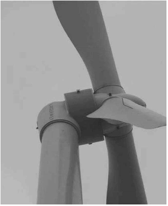
Fig. 1. Photo of a 1.5-MW direct-drive wind turbine with permanent-magnet
generator of Zephyros. Source: Zephyros BV.
power electronic converter feeding the rotor winding with
a power rating of approximately 30% of the rated power
of the turbine.
3) Since 1991, there have also been wind turbine manufac-
turers proposing gearless generator systems with the so-
called direct-drive generators, mainly to reduce failures in
gearboxes and to lower maintenance problems. A power
electronic converter for the full-rated power is then neces-
sary for the grid connection. The low-speed high-torque
generators and the fully rated converters for these wind
turbines are rather expensive.
Most direct-drive turbines being sold at the moment have syn-
chronous generators with electrical excitation. However, [3]–[7]
claim benefits for permanent magnet excitation, which elim-
inates the excitation losses. In this paper, this difference is
quantified. Fig. 1 depicts an example of a wind turbine with
a permanent-magnet direct-drive generator [8].
For the increasing power levels and decreasing speeds, these
direct-drive generators are becoming larger and even more ex-
pensive. Therefore, it has been proposed to use a single-stage
gearbox (with a gear ratio in the order of 6 or higher) and a
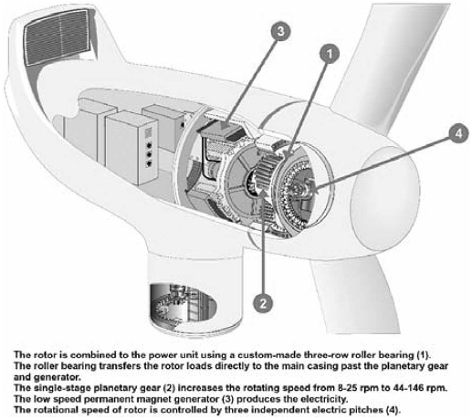
permanent-magnet generator [7]. This system, called the multi-
brid system, is illustrated in Fig. 2.
On the one hand, the resulting system combines some of
the disadvantages of both the geared and direct-drive systems:
the system has a gearbox and it has a special and therefore
expensive generator and a fully rated converter. On the other
hand, compared to direct-drive systems, a significant decrease
0885-8969/$20.00 © 2006 IEEE

726 IEEE TRANSACTIONS ON ENERGY CONVERSION, VOL. 21, NO. 3, SEPTEMBER 2006
Fig. 2. Sketch of the system with a single-stage gearbox. Source: WinWinD.
in the generator cost and an increase in the generator efficiency
can be obtained.
Further, the question arises whether this system with a single-
stage gearbox could be used in combination with a DFIG. Be-
cause the generator torque is still rather high and the speed rather
low, the generator can be expected to have a large diameter
and air gap, and therefore a high magnetizing current and high
losses. However, the rating of the converter could be reduced to
roughly 30%, giving an important benefit in cost and efficiency.
This new system is introduced and further investigated in this
paper.
For both systems with a single-stage gearbox, the use of a
gearbox leads to a significant reduction of the external dimen-
sions, enabling the installation of such a 3-MW wind turbine on
locations that are currently limited from a logistic point of view
to 1.5-MW turbines.
The objective of this paper, therefore, is to compare five wind
turbine generator systems, namely:
1) the DFIG3G as currently used;
2) the DDSG as currently used;
3) the DDPMG;
4) the PMG1G;
5) the DFIG1G.
To compare the five generator systems, a 3-MW, 15-r/min
wind turbine is used. For this turbine, an approximate design
of the generators is made to get indications of weight and cost.
The differences in annual energy yield are calculated for a given
wind climate. This comparison and the proposal to use a DFIG
in combination with a single-stage gearbox are the original con-
tributions of this paper.
An early comparison of the efficiency of three wind turbine
generator systems is given in [9]. In [6] and [7], more genera-
tor systems were compared and more criteria were taken into
account. The contribution of this paper is that it introduces the
TABLE I
M
ODELING CHARACTERISTICS
DFIG1G, and compares it with four other generator systems.
It also quantifies the difference between the electrical-excited
direct-drive generator and the PM direct-drive generator.
The paper starts with a section about modeling of the wind
turbine, the gearbox, the converter, and the generator. Next the
five generator designs are briefly described and the resulting
performance is given. The paper concludes with a comparison
of the five generator concepts.
II. M
ODELING THE GENERATOR CONCEPTS
A. Wind Turbine Modeling
Table I gives t he characteristics of the wind turbine that was
used to compare the different generator systems. Using these
characteristics, the available s haft power P can be calculated as
a function of the wind speed as [2], [10]
P =
1
2
ρ
air
C
p
(λ, θ)πr
2
v
3
w
(1)
where ρ
air
is the mass density of air, r is the wind turbine
rotor radius, v
w
is the wind speed, and C
p
(λ, θ) is the power
coefficient or the aerodynamic efficiency, which is a function of
the tip speed ratio λ (tip speed divided by wind speed) and the
pitch angle θ.
Fig. 3 illustrates the rotor speed, which is assumed to be pro-
portional to the wind speed at maximum aerodynamic efficiency
at low wind speeds and equal to the rated rotor speed at higher
wind speeds (above 9 m/s). At wind speeds above the rated

POLINDER et al.: COMPARISON OF DIRECT-DRIVE AND GEARED GENERATOR CONCEPTS FOR WIND TURBINES 727
Fig. 3. Rotor speed and Weibull distribution of the wind as a function of wind
speed.
wind speed, the blades are pitched to reduce the aerodynamic
efficiency and so the power.
For energy yield calculations, an average wind speed of 7 m/s
with a Weibull distribution [10] is used as illustrated in Fig. 3.
Integrating the area below the curve gives a value of 1.
Table I also gives some approximate numbers for the cost of
the rest of the wind turbine. Because the paper concentrates on
the generator system, these numbers are not extensively vali-
dated and must be seen only as indicators.
B. Gearbox Modeling
The gear ratio of the single-stage gearbox is chosen as 6.
Some references suggest higher gear ratios [7]. However, at the
moment, this is not seen as proven technology with a guaranteed
lifetime. From the commercially available gearboxes, it appears
to be cheaper to use gearboxes with more stages for higher gear
ratios. A cost estimate of the gearbox is given in Table I.
According to [11], a viscous loss of 1% of the rated power
per gearbox stage is a reasonable model. This means that the
losses are proportional to the speed
P
gear
= P
gearm
n
n
rated
(2)
where P
gearm
is the loss in the gearbox at rated speed (3%
of rated power for a three-stage gearbox [11] and 1.5% for a
single-stage gearbox, see Table I), n is the rotor speed (r/min),
and n
rated
is the rated rotor speed (r/min).
C. Converter Modeling
A back-to-back voltage source inverter is used to ensure that
the generator currents and the grid currents are sinusoidal. A
cost estimate is given in Table I.
There are various ways of modeling converter losses [12].
The model used here divides them into three parts [13]:
1) a small part that is constant and consists of power dis-
sipated in power supplies, gate drivers, control, cooling
systems and so on [9];
2) a large part that is proportional to the current and consists
of switching losses and conduction losses;
3) a part that is proportional to the current squared and con-
sists of conduction losses because the on-state voltage of
a semiconductor increases with the current.
Therefore, the losses in the converter P
conv
are modeled as
P
conv
=
P
convm
31
1+10
I
s
I
sm
+5
I
2
s
I
2
sm
+10
I
g
I
gm
+5
I
2
g
I
2
gm
(3)
where P
convm
is the dissipation in the converter at rated power
(3% of the rated power of the converter, see Table I), I
s
is the
generator side converter current ,I
sm
is the maximum generator
side converter current, I
g
is the grid side converter current, and
I
gm
is the maximum grid side converter current.
D. Generator Modeling
The different generators are modeled using equivalent circuit
models. This section describes the equations used to determine
the parameters of the equivalent circuit. The machine parameters
are calculated in conventional ways [9].
The following assumptions are used in the calculations.
1) Space harmonics of the magnetic flux density distribu-
tion in the air gap are negligible; only the fundamental is
considered.
2) The magnetic flux density crosses the air-gap perpendic-
ularly.
Slot, air-gap, and end-winding leakage inductances are cal-
culated as given in [14]. The magnetizing inductance of an AC
machine is given by [14], [15]
L
sm
=
6µ
0
l
s
r
s
(k
w
N
s
)
2
p
2
g
eff
π
(4)
where l
s
is the stack length in axial direction, r
s
is the stator
radius, N
s
is the number of turns of the phase winding, k
w
is
the winding factor [14], [15], p is the number of pole pairs, and
g
eff
is the effective air gap.
The effective air gap of the machine depends on the t ype of
machine. For all machine types, it can be written as
g
eff
= k
sat
k
Cs
k
Cr
g +
l
m
µ
rm
(5)
where k
sat
is a factor representing the reluctance of the iron in
the magnetic circuit, k
Cs
is the Carter factor for the stator slots
[14], k
Cr
is the Carter factor for the rotor slots (if present) [14], g
is the mechanical air gap, µ
rm
is the relative recoil permeability
of the magnets, and l
m
is the magnet length in the direction of the
magnetization (which is zero in a machine without permanent
magnets).
The Carter factor is given by [14], [16]
k
C
=
τ
s
τ
s
g
1
γ
g
1
= g +
l
m
µ
rm
γ =
4
π
b
so
2g
1
arctan
b
so
2g
1
log
1+
b
so
2g
1
2
(6)
where τ
s
is the slot pitch and b
so
is the slot opening width.
The factor representing the reluctance of the iron of the mag-
netic circuit is calculated as [17]
k
sat
=1+
1
H
g
g
eff
l
Fe
0
H
Fe
dl
Fe
(7)
where H
Fe
is the magnetic field intensity in the iron, estimated
from the BH curve.

728 IEEE TRANSACTIONS ON ENERGY CONVERSION, VOL. 21, NO. 3, SEPTEMBER 2006
Fig. 4. Sketch of a cross section of four poles of a permanent magnet syn-
chronous machine with full pitch winding.
In permanent-magnet machines, this factor representing sat-
uration is much smaller than in the other machines because the
effective air gap is much larger due to the low permeability of
the magnets.
Using Ampere’s circuital law, the BH characteristic of a rare-
earth permanent magnet and the magnetic flux continuity, the
flux density above a magnet in the air gap of a permanent-magnet
machine (Fig. 4) can be calculated as [15]
ˆ
B
g
=
l
m
µ
rm
g
eff
B
rm
(8)
where B
rm
is the remanent flux density of the magnets (1.2 T).
Using Fourier analysis, the fundamental space harmonic of
this flux density can be calculated as [15], [16]
ˆ
B
g
=
l
m
µ
rm
g
eff
B
rm
4
π
sin
πb
p
2τ
p
(9)
where τ
p
is the pole pitch and b
p
is the width of the magnet.
The no-load (motional) voltage induced by this flux density
in a stator winding can be calculated as [15], [16]
E
p
=
2k
w
N
s
ω
m
r
s
l
s
ˆ
B
g
(10)
where ω
m
is the mechanical angular speed of the rotor.
The copper losses are calculated from the currents and the
resistances. The phase resistance is calculated as
R
s
=
ρ
Cu
l
Cus
A
Cus
(11)
where ρ
Cu
is the resistivity of copper, A
Cus
is the cross-sectional
area of the conductor, and l
Cus
is the length of the conductor of
the phase winding.
The length of the conductor is calculated as the number of
turns multiplied by the length of a turn, where the length of a
turn is estimated as twice stack length (in the slots) plus four
times the pole pitch (for the end windings)
l
Cus
= N
s
(2l
s
+4τ
p
). (12)
The cross-section area of the conductor is the available slot
area multiplied by the fill factor divided by the number of turns
per slot:
A
Cus
=
pqk
sfil
b
sav
h
s
N
s
(13)
where q is the number of slots per pole per phase, k
sfil
is the s lot
fill factor (60%), b
sav
is the average slot width, and h
s
is the slot
height.
The specific iron losses (the iron losses per unit mass) are
calculated using [14], [15]
P
Fe
=2P
Fe0 h
f
e
f
0
ˆ
B
Fe
ˆ
B
0
2
+2P
Fe0 e
f
e
f
0
2
ˆ
B
Fe
ˆ
B
0
2
(14)
where f
e
is the frequency of the field in the iron, P
Fe0 h
is the
hysteresis loss per unit mass at the given angular frequency f
0
and flux density B
0
(Table I), and P
Fe0 e
is the eddy current loss
per unit mass at the given angular frequency f
0
and flux density
B
0
(Table I).
The factor 2 is included in this equation because the flux den-
sities do not change sinusoidally and they are not sinusoidally
distributed, which increases the iron losses. High quality lami-
nations are used to limit the iron losses in the generators with
higher frequencies.
To calculate the total iron losses, the specific iron losses in
the different parts (teeth and yokes) are evaluated, multiplied by
the weight of these parts, and added.
To find out the cost of a generator, the masses of iron, copper,
and magnets are calculated and multiplied by the assumed cost
per kilogram of the material (see Table I).
III. G
ENERATOR DESIGN AND PERFORMANCE
A. DFIG3G
The number of pole pairs of the DFIG3G is chosen as 3.
Because the stator is directly connected to the 50-Hz grid, the
synchronous speed is 1000 r/min. With a gear ratio of 80, the
rated speed of the generator is 1200 r/min, so that at rated speed,
there is still some margin for control purposes.
The DFIG3G has an air-gap radius of 0.42 m and a stack
length of 0.75 m. Other important dimensions are given in
Table II.
Fig. 5 depicts two induction-machine equivalent circuits. The
rotor side parameters are all referred parameters. The parame-
ters of the second equivalent circuit can be calculated from the
parameters of the first in the following way [15]:
L
s
= L
sσ
+ L
sm
;
R
R
=
R
r
L
2
s
L
2
sm
L
L
=
L
sσ
L
s
L
sm
+
L
rσ
L
2
s
L
2
sm
. (15)
To simplify the calculations, the second equivalent circuit
has been used. It is further assumed that the converter controls
the rotor current in such a way that the magnetizing current is
confined to the stator and that the transformed rotor current I
R
is in phase with the voltage applied to the inductance L
s
.
Fig. 6 depicts s ome results from the model as a function of
the wind speed. Voltage, current, power, generator efficiency,
generator system efficiency (including losses in the converter
and the gearbox), and losses are depicted. The annual energy

POLINDER et al.: COMPARISON OF DIRECT-DRIVE AND GEARED GENERATOR CONCEPTS FOR WIND TURBINES 729
TABLE II
M
AIN DIMENSIONS,PARAMETERS,WEIGHTS,COST, AND ANNUAL
ENERGY OF THE FIVE GENERATOR SYSTEMS
dissipation, determined from a combination of the losses with
the Weibull distribution, is also depicted in Fig. 6. Table II gives
the annual energy yield and the annual dissipation. It also gives
cost estimates.
The losses in the gearbox dominate the losses in this generator
system: Roughly 70% of the annual energy dissipation in t he
generator system is in the gearbox.
B. DDSG
The air-gap diameter of the DDSG is chosen to be 5 m. From
the electromagnetic point of view, larger air-gap diameters are
better, but mechanical design, construction and transportation
Fig. 5. IEEE recommended equivalent circuit of the induction machine and
the applied Γ-type equivalent circuit [15].
Fig. 6. Characteristics of the DFIG3G.
Fig. 7. Sketch of a linearized cross section of two poles of an electrically
excited synchronous machine.
become more difficult. This 5-m air-gap diameter is a compro-
mise between these criteria.
Fig. 7 depicts a cross section of two poles of the machine. The
number of slots per pole per phase is two. Increasing this number
makes the machine heavier and more expensive because of the
increasing dimensions of end-windings and yokes. Decreasing
this number results in a significant increase in the excitation
losses, mainly in part load. Table II gives some other important
dimensions.
Fig. 8 depicts the equivalent circuit of the DDSG and the ap-
plied phasor diagram. The phase current leads the phase voltage
a little in order to reduce saturation and excitation losses while a
larger rating of the converter is not necessary. A more extensive
description of the model for saturation is given in [17].

Citations
More filters
Journal ArticleDOI
TL;DR: Considering future bottlenecks in raw materials, options for the recycling of rare-earth intermetallics for hard magnets will be discussed and their potential impact on energy efficiency is discussed.
Abstract: A new energy paradigm, consisting of greater reliance on renewable energy sources and increased concern for energy effi ciency in the total energy lifecycle, has accelerated research into energy-related technologies. Due to their ubiquity, magnetic materials play an important role in improving the effi ciency and performance of devices in electric power generation, conditioning, conversion, transportation, and other energy-use sectors of the economy. This review focuses on the state-of-the-art hard and soft magnets and magnetocaloric materials, with an emphasis on their optimization for energy applications. Specifi cally, the impact of hard magnets on electric motor and transportation technologies, of soft magnetic materials on electricity generation and conversion technologies, and of magnetocaloric materials for refrigeration technologies, are discussed. The synthesis, characterization, and property evaluation of the materials, with an emphasis on structure‐property relationships, are discussed in the context of their respective markets, as well as their potential impact on energy effi ciency. Finally, considering future bottlenecks in raw materials, options for the recycling of rare-earth intermetallics for hard magnets will be discussed.

2,465 citations

Journal ArticleDOI
H. Li1, Zhe Chen1
TL;DR: An overview of different wind generator systems and their comparisons are presented in this article, where the quantitative comparison and market penetration of different WG systems are presented. And the developing trends of wind generator system and appropriate comparison criteria are discussed.
Abstract: With rapid development of wind power technologies and significant growth of wind power capacity installed worldwide, various wind turbine concepts have been developed. The wind energy conversion system is demanded to be more cost-competitive, so that comparisons of different wind generator systems are necessary. An overview of different wind generator systems and their comparisons are presented. First, the contemporary wind turbines are classified with respect to both their control features and drive train types, and their strengths and weaknesses are described. The promising permanent magnet generator types are also investigated. Then, the quantitative comparison and market penetration of different wind generator systems are presented. Finally, the developing trends of wind generator systems and appropriate comparison criteria are discussed. It is shown that variable speed concepts with power electronics will continue to dominate and be very promising technologies for large wind farms. The future success of different wind turbine concepts may strongly depend on their ability of complying with both market expectations and the requirements of grid utility companies.

1,023 citations


Cites background from "Comparison of direct-drive and gear..."

  • ...1 Performance comparison of different wind generator systems Some comparisons of different wind generator system have been conducted by some researchers [8–13, 17, 19, 24, 26, 39–41]....

    [...]

  • ...Additionally, a variety of innovative concepts of wind turbines appear, for example, an interesting alternative may be a mixed solution with a gearbox and a smaller low speed permanent magnet synchronous generator (PMSG) [7–9], because direct-drive wind generators are becoming larger and even more expensive for increasing power levels and decreasing rotor speeds....

    [...]

  • ...3 Discussions of comparison criteria Various criteria may be used for comparing different wind generator systems, including the torque density, the cost per torque, the efficiency, the active material weight, the outer diameter, the total length, the total volume, the total generator cost, the annual energy yield, the energy yield per cost, the cost of energy and so on [8, 9, 12, 13, 16, 17, 21, 25]....

    [...]

  • ...[9] have also presented a detailed comparison of five 3 MW different generator systems for variable speed wind turbine concepts, which are a DFIG system with three-stage gearbox (DFIG 3G), a direct-...

    [...]

  • ...† DFIG 3G is the lightest and low-cost solution with standard components according to [9]....

    [...]

Journal ArticleDOI
TL;DR: The most-adopted wind-turbine systems, the adopted generators, the topologies of the converters, the generator control and grid connection issues, as well as their arrangement in wind parks are reviewed.
Abstract: Multimegawatt wind-turbine systems, often organized in a wind park, are the backbone of the power generation based on renewable-energy systems. This paper reviews the most-adopted wind-turbine systems, the adopted generators, the topologies of the converters, the generator control and grid connection issues, as well as their arrangement in wind parks.

860 citations

Journal ArticleDOI
TL;DR: In this paper, power converters are classified into single and multicell topologies, with attention to series connection and parallel connection either electrical or magnetic ones (multiphase/windings machines/transformers).
Abstract: The steady growth of installed wind power together with the upscaling of the single wind turbine power capability has pushed the research and development of power converters toward full-scale power conversion, lowered cost pr kW, increased power density, and also the need for higher reliability. In this paper, power converter technologies are reviewed with focus on existing ones and on those that have potential for higher power but which have not been yet adopted due to the important risk associated with the high-power industry. The power converters are classified into single- and multicell topologies, in the latter case with attention to series connection and parallel connection either electrical or magnetic ones (multiphase/windings machines/transformers). It is concluded that as the power level increases in wind turbines, medium-voltage power converters will be a dominant power converter configuration, but continuously cost and reliability are important issues to be addressed.

797 citations


Cites background from "Comparison of direct-drive and gear..."

  • ...3b compares the direct driven (DD) synchronous generator (SG) with the 3 stage gearbox (3G) Doubly-Fed Induction Generator (DFIG), using the latter as the base value for both weight and losses [8]-[9]....

    [...]

Journal ArticleDOI
18 May 2015
TL;DR: The most successful generator-converter configurations are addressed along with few promising topologies available in the literature from the market based survey, and the past, present and future trends in megawatt WECS are reviewed in terms of mechanical and electrical technologies, integration to power systems, and control theory.
Abstract: This paper presents a comprehensive study on the state-of-the-art and emerging wind energy technologies from the electrical engineering perspective. In an attempt to decrease cost of energy, increase the wind energy conversion efficiency, reliability, power density, and comply with the stringent grid codes, the electric generators and power electronic converters have emerged in a rigorous manner. From the market based survey, the most successful generator-converter configurations are addressed along with few promising topologies available in the literature. The back-to-back connected converters, passive generator-side converters, converters for multiphase generators, and converters without intermediate dc-link are investigated for high-power wind energy conversion systems (WECS), and presented in low and medium voltage category. The onshore and offshore wind farm configurations are analyzed with respect to the series/parallel connection of wind turbine ac/dc output terminals, and high voltage ac/dc transmission. The fault-ride through compliance methods used in the induction and synchronous generator based WECS are also discussed. The past, present and future trends in megawatt WECS are reviewed in terms of mechanical and electrical technologies, integration to power systems, and control theory. The important survey results, and technical merits and demerits of various WECS electrical systems are summarized by tables. The list of current and future wind turbines are also provided along with technical details.

694 citations


Cites background from "Comparison of direct-drive and gear..."

  • ...tear, reduced life span, reduced efficiency and need for regular maintenance [30], [50]....

    [...]

  • ...5 times heavier compared to the three-stage gearbox based induction generators [50], [54]....

    [...]

References
More filters
Book
01 Jan 1988

2,810 citations

Dissertation
01 Jan 1996
TL;DR: In this paper, the authors presented an investigation of how a direct-driven wind turbine generator should be designed and how small and efficient such a generator will be, and a radial-flux permanent-magnet generator connected to a forced-commutated rectifier was chosen for a detailed theoretical investigation.
Abstract: This thesis presents an investigation of how a direct-driven wind turbine generator should be designed and how small and efficient such a generator will be. Advantages and disadvantages of various types of direct-driven wind turbine generators are discussed, and a radial-flux permanent-magnet generator connected to a forced-commutated rectifier is chosen for a detailed theoretical investigation. Further, a design method is developed for the electromagnetic part of the chosen generator type. The generator is optimized with a simplified cost function which, besides including the cost of the active generator parts and the cost of the structure, also includes the cost of the average losses. Therefore, a method to calculate the average losses is derived. The design method is used to investigate the optimization of a 500 kW generator, and the size, efficiency and active weight of optimized generators from 30 kW to 3 MW are presented. A result of the investigation is that the outer diameters of the direct-driven generators are only slightly larger than the width of conventional wind energy converter nacelles. A comparison of average efficiency shows that direct-driven generators, including the losses in the frequency converters, are more efficient than conventional wind energy converter drive trains. Compared with other direct-driven generators, the proposed generator type is small, mainly because of the forced-commutated rectifier and because the generator is not required to produce a pull-out torque higher than the rated torque.

277 citations

Book
01 Jan 1992
TL;DR: In this article, the authors present an expanded discussion of diode rectifiers and thyristor converters as well as a step-by-step design approach and a computer simulation of power electronics which introduces numerical techniques and commonly used simulation packages such as PSpice, MATLAB and EMTP.
Abstract: Market_Desc: · Electrical Engineering Students · Electrical Engineering Instructors· Power Electronics Engineers Special Features: · Easy to follow step-by-step in depth treatment of all the theory.· Computer simulation chapter describes the role of computer simulations in power electronics. Examples and problems based on Pspice and MATLAB are included.· Introductory chapter offers a review of basic electrical and magnetic circuit concepts.· A new CD-ROM contains the following:· Over 100 of new problems of varying degrees of difficulty for homework assignments and self-learning.· PSpice-based simulation examples, which illustrate basic concepts and help in design of converters.· A newly-developed magnetic component design program that demonstrates design trade-offs.· PowerPoint-based slides, which will improve the learning experience and the ease of using the book About The Book: The text includes cohesive presentation of power electronics fundamentals for applications and design in the power range of 500 kW or less. It describes a variety of practical and emerging power electronic converters made feasible by the new generation of power semiconductor devices. Topics included in this book are an expanded discussion of diode rectifiers and thyristor converters as well as chapters on heat sinks, magnetic components which present a step-by-step design approach and a computer simulation of power electronics which introduces numerical techniques and commonly used simulation packages such as PSpice, MATLAB and EMTP.

242 citations


"Comparison of direct-drive and gear..." refers background or methods in this paper

  • ...where ls is the stack length in axial direction, rs is the stator radius, Ns is the number of turns of the phase winding, kw is the winding factor [14], [15], p is the number of pole pairs, and geff is the effective air gap....

    [...]

  • ...The no-load (motional) voltage induced by this flux density in a stator winding can be calculated as [15], [16]...

    [...]

  • ...The magnetizing inductance of an AC machine is given by [14], [15]...

    [...]

  • ...Using Fourier analysis, the fundamental space harmonic of this flux density can be calculated as [15], [16]...

    [...]

  • ...The parameters of the second equivalent circuit can be calculated from the parameters of the first in the following way [15]:...

    [...]

Journal ArticleDOI
TL;DR: In this paper, the average efficiency of three 500 kW wind energy converters is compared, and it is shown that a variable-speed generator system can be almost as efficient as one for constant speed, although it has much higher losses at rated load.
Abstract: This paper presents a method to calculate the average efficiency from the turbine shaft to the grid in wind energy converters. The average efficiency of three 500 kW systems are compared. The systems are: a conventional grid-connected four-pole induction generator equipped with a gear, a variable-speed synchronous generator equipped with a gear and a frequency converter, and a directly driven variable-speed generator equipped with a frequency converter. In this paper it is shown that a variable-speed generator system can be almost as efficient as one for constant speed, although it has much higher losses at rated load. The increased turbine efficiency that variable speed leads to has not been included in this paper. It is also found that a directly driven generator can be more efficient than a conventional four-pole generator equipped with a gear.

185 citations


"Comparison of direct-drive and gear..." refers methods in this paper

  • ...The model used here divides them into three parts [13]: 1) a small part that is constant and consists of power dissipated in power supplies, gate drivers, control, cooling systems and so on [9]; 2) a large part that is proportional to the current and consists of switching losses and conduction losses; 3) a part that is proportional to the current squared and con-...

    [...]

  • ...The machine parameters are calculated in conventional ways [9]....

    [...]

26 Jan 2004
TL;DR: In this article, a TFPM machine with toothed rotor was proposed to reduce the cost of a direct-drive generator for wind turbines, where the stator is single-sided, the rotor PM and flux concentrators are independent from the build-up of mechanical tolerances, and the flux circulation allows laminated steel to be used in the rotor core.
Abstract: The thesis deals with the issue of cost reduction in direct-drive generators for wind turbines. Today, the combination gearbox-medium-speed (1000-2000 rpm) induction generator largely dominates the market of MW-scale wind turbines. This is due to the lower costs of the gearbox option compared to the costs of gearless systems. Nevertheless, there is an acute interest among researchers and wind turbine suppliers in the possibility of removing gears and slip rings from the drive train, leading to lower maintenance (no oil is required and slip rings can be avoided) and higher reliability due to the absence of wear between gears. The direction followed by the thesis is the investigation and comparison of various permanent magnet (PM) machine topologies. The aim is to identify the topology(ies) with the lowest cost/torque and highest torque/ mass. A new TFPM geometry, called TFPM machine with toothed rotor, is derived in the. The new machine topology has the following characteristics: the stator is single-sided, the rotor PM and flux concentrators are independent from the build-up of mechanical tolerances, the installation of rotor parts (PM and flux concentrators) can be automated and the flux circulation allows laminated steel to be used in the stator core. A prototype of the TFPM machine with toothed rotor is presented. The comparison between TFPM machines with toothed rotor and conventional PM synchronous machines is discussed. Comparison of the cost/torque and torque/mass of the two machine topologies for diameters ranging between 0.5 m and 3.0 m showed favorable expected performances of the TFPM machine with toothed rotor for diameters of 0.5 m and 1.0 m. However, diameters larger than 1.0 m favored the conventional PM synchronous machine with/without flux-concentration. Using the results of the optimization process, the costs of active material are computed for a 1.5 MW wind turbine. It is found that active material represents about 5% of the total turbine cost, while previous estimates indicated that the generator costs are rather between 30% and 40% of a complete direct-drive wind turbine. Therefore, further optimiza¬tion of direct-drive machines should also include the costs of manufacturing and the costs of the mechanical structure.

154 citations


"Comparison of direct-drive and gear..." refers background in this paper

  • ...However, [3]–[7] claim benefits for permanent magnet excitation, which elim-...

    [...]

  • ...the cost of the permanent magnets and the power electronics is decreasing and because further optimization and integration of the generator system is possible [3], [18], [19]....

    [...]

Frequently Asked Questions (18)
Q1. What have the authors contributed in "Comparison of direct-drive and geared generator concepts for wind turbines" ?

The objective of this paper is to compare five different generator systems for wind turbines, namely the doubly-fed induction generator with three-stage gearbox ( DFIG3G ), the directdrive synchronous generator with electrical excitation ( DDSG ), the direct-drive permanent-megnet generator ( DDPMG ), the permanent-magnet generator with single stage gearbox ( PMG1G ), and the doubly-fed induction generator with single-stage gearbox ( DFIG1G ). 

Very important design aspects for which further work is needed are reliability and availability [ 20 ]. 

The phasecurrent is in the middle between the terminal voltage and the voltage induced by the magnets in order to reduce the saturation and to get a compromise between the converter rating and the generator rating. 

The phase current leads the phase voltage a little in order to reduce saturation and excitation losses while a larger rating of the converter is not necessary. 

Manufacturers supplying the DFIG3G use generator and converter components which are close to industrial standards yielding benefits in standardization, cost, and reliability. 

With a gear ratio of 80, the rated speed of the generator is 1200 r/min, so that at rated speed, there is still some margin for control purposes. 

The parameters of the second equivalent circuit can be calculated from the parameters of the first in the following way [15]:Ls = Lsσ + Lsm;RR = RrL2 sL2smLL = LsσLs Lsm + LrσL2 sL2sm . (15)To simplify the calculations, the second equivalent circuit has been used. 

Using these characteristics, the available shaft power P can be calculated as a function of the wind speed as [2], [10]P = 1 2 ρairCp(λ, θ)πr2v3w (1)where ρair is the mass density of air, r is the wind turbine rotor radius, vw is the wind speed, and Cp(λ, θ) is the power coefficient or the aerodynamic efficiency, which is a function of the tip speed ratio λ (tip speed divided by wind speed) and the pitch angle θ. 

The only commercially successful large direct-drive wind turbine manufacturer, Enercon, uses this system but they claim other benefits from the system. 

The losses in the gearbox dominate the losses in this generator system: Roughly 70% of the annual energy dissipation in the generator system is in the gearbox. 

The factor representing the reluctance of the iron of the magnetic circuit is calculated as [17]ksat = 1 + 1Hggeff ∫ lFe 0 HFedlFe (7)where HFe is the magnetic field intensity in the iron, estimated from the BH curve. 

Because it is mainly built from standard components consisting of copper and iron, major improvements in performance or cost reductions cannot be expected. 

The magnetizing current of this induction machine is rather large due to the considerable air gap and the high number of pole pairs. 

Because the paper concentrates on the generator system, these numbers are not extensively validated and must be seen only as indicators. 

In permanent-magnet machines, this factor representing saturation is much smaller than in the other machines because the effective air gap is much larger due to the low permeability of the magnets. 

The annual energydissipation, determined from a combination of the losses with the Weibull distribution, is also depicted in Fig. 

The annual energy dissipation, determined from a combination of the losses with the Weibull distribution, is also depicted in Fig. 13. 

Iron losses are not negligible; at wind speeds up to 8 m/s, they are larger than the copper losses and over 15% of the annual dissipation in the generator system is in the iron.