scispace - formally typeset
Search or ask a question
Journal ArticleDOI

Deviation of a machined surface in flank milling

TL;DR: In this article, the authors present the results of an identification procedure of the coefficients of a force model for a given tool workpiece couple for the prediction of the defects of the tool during the cutting.
Abstract: The flatness defects observed in flank milling with cutters of long series are mainly due to the tool deflections during the machining process. This article present the results of an identification procedure of the coefficients of a force model for a given tool workpiece couple for the prediction of the defects of the tool during the cutting. The calibration method proposed meets a double aim: to define an experimental protocol that takes the industrial constraints of time and cost into account and to work out a protocol which minimizes uncertainties likely to alter the interpretation of the results (environmental, software or mechanical uncertainties). For that, the procedure envisages the machining of a simple plane starting from a raw part formed by a tilted plane, allowing for the variation of the tool engagement conditions. The tool deviation during the cutting process is indirectly identified by measuring the machined surface. The observed straightness defect conditions can be explained by the evolution of the cutting pressures applied to the cutting edges in catch during the cutter rotation. The precision was considerably improved by the taking into account of the cutter slope defect in the calculation of the load applied to the tool. After identification of the tool-workpiece couple, the prediction model was applied to some examples and allowed to determine the variations of form and position of the surface points with a margin of 5%.

Summary (3 min read)

3.1. Introduction

  • The determination of the force model coefficients is a significant stage for the prediction of the machining defects.
  • The results obtained always depend on the conditions of realization of the tests and on the hypotheses of calculation set up.
  • The most current identification strategies concern the direct measurement of characteristic components of the cutting process for a tool-workpiece couple (Kr0, Kt0 characterized) for given conditions.
  • The examination is also rather delicate because there are generally several teeth in catch.
  • The opposite problem is then solved by comparing the theoretical deformation of the tool with the deformation of the machined surface.

3.2.1. Principles of the test selected

  • Taking the constraints previously evoked into account, the authors define a test protocol based on the flank milling in concordance of a simple plane which is realizable on any milling machine.
  • The reference zones which require two narrow bands with a small depth of cut of 0.3 mm in order to limit the cutting forces and the tool deflections A lateral slot that lets the tool end out of the workpiece material.
  • In order to isolate the influence of the tool deflection on the part defect, the tool end is left free to avoid the disturbances caused by a parasitic friction of the tool end.

3.2.2. Experimental validation of the assumptions

  • To obtain an experimental model representing the cutting process as precisely as possible, the following hypotheses are posed: 1. The part is very rigid and firmly taken in on the part holder.
  • The induced deflection is obtained using two comparators for one point of load (Fig. 5).
  • The point A, located near the spindle nose, is retained as the presumed housing point.
  • The maximum deformation noted is lower than 15 µm and will be neglected too.
  • The authors finally consider that the dynamics of the machine spindles does not disturb machining, because the machined surface is a simple plane which is milled at constant feedrate with a long stabilization and acceleration distance before machining the central part (section 3).

3.2.3. Principles of measurement

  • From an operational point of view, the identification consists in machining the test part and measuring the defects of the machined surface.
  • This statement gives the actual value of the deformation at each point of a measurement grid posed on the machined surface.
  • To measure the defects of the test part correctly, a reference mark was conceived on the basis of reference surfaces (Fig. 6).
  • It thus allows for an effective registration between the reference mark part and the reference mark of the CMM machine.
  • Within the framework of this article, the part test was machined under the following conditions: HSS tool whose diameter is 20 mm and whose active length is 88 mm Machining on a vertical milling center Vc=25 m/min fz=0.2 mm/tooth Nt=4 teeth.

3.3. Experimental results

  • Machining revealed the presence of a flatness defect whose shape is a wave, reflecting the varying distribution of the forces in time.
  • Only the central zone of the cloud of measured points corresponding to the permanent mode (represented on the Fig. 7) is used to identify the deflection model.
  • A software model makes it possible to solve the preceding system.
  • In spite of a light effect due to the variation of the tool workpiece couple according to the cutting speed, each test made it possible to note that the variations of the points and the form of the defects previously noted were quasi imperceptible to speed thus to time.

4.1. Originality of the method

  • The originality of this work lies in the consideration of this paradox and on its resolution by avoiding iterative procedures.
  • Fig. 9 goes back onto the various stages of the calculation of the theoretical tool deformation.
  • The normal differences between the nominal plane and the machined plane are then measured for each point of this grid.
  • To calculate the tool deflection at each point of the grid, it is necessary to first determine the tool engagement angles in the workpiece material.
  • The authors then simultaneously determine the position of the teeth in catch when the point generated is one of the points of the grid by using an evolution model of the teeth location similar to Choi’s [27].

4.2. Calculation of the engagement angles

  • This paragraph aims to specify the details of the calculation of the engagement angles according to the tool deformation.
  • Fig. 10 presents a case where there is one tooth engaged in the workpiece material.
  • During machining, the tool leans under the cutting forces.
  • The tool slope must be taken into account in the calculation of the extreme point position.
  • The coordinates of the exit point of the tool cutting edge are calculated by intersection between the helix and the rough surface.

4.3. Numerical results

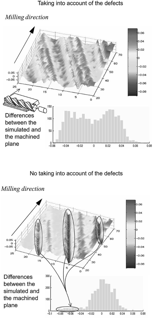
  • The taking into account of the slope defect and of the deflection defect in the identification procedure is very significant.
  • This result is visible on Fig. 13 which compares the error between the simulated points cloud and the measured points cloud taking the deviation and the slope of the tool on point P in the calculation of a into account or not.
  • With the taking into account of the defection defect and of the slope defect, the differences are regularly distributed between 0.04 and 0.05 mm on all the surfaces.

5. Application

  • The tool workpiece couple was identified with the preceding procedure.
  • The engagement angles are thus calculated starting from this deviation and from the radial engagement of the section studied, always by intersection with the helix representing the cutting edge.
  • The results obtained were always satisfactory with the same order of magnitude of uncertainty on the hypothesis.
  • It would now be necessary to develop a campaign of tests on a greater diversity of tool and parts materials with different tool geometries, in particular with odd numbers of teeth that give a quadratic moment Igy which is not constant.
  • This result should then make it possible to implement machining tool paths corrections, in order to make up for the tool deflection so that the machined surface approaches the expected nominal form as much as possible.

Did you find this useful? Give us your feedback

Content maybe subject to copyright    Report

Deviation of a machined surface in flank milling
A. Larue
a,
, B. Anselmetti
a,b
a
Laboratoire Universitaire de Recherche en Production Automatise
´
e, Ecole Normale Supe
´
rieure de Cachan, 61, av du pre
´
sident Wilson, 94235
Cachan Cedex, France
b
Institut Universitaire de Technologie de Cachan, 9, av de la division Leclerc 94234 Cachan Cedex, France
The flatness defects observed in flank milling with cutters of long series are mainly due
to the tool deflections during the machining
process. This article present the results of an identification procedure of the coefficients of a force model for a given tool workpiece
couple for the prediction of the defects of the tool during the cutting. The calibration method proposed meets a double aim: to define
an experimental protocol that takes the industrial constraints of time and cost into account and to work out a protocol which
minimizes uncertainties likely to alter the interpretation of the results (environmental, software or mechanical uncertainties). For that,
the procedure envisages the machining of a simple plane starting from a raw part formed by a tilted plane, allowing for the variation
of the tool engagement conditions. The tool deviation during the cutting process is indirectly identified by measuring the machined
surface. The observed straightness defect conditions can be explained by the evolution of the cutting pressures applied to the cutting
edges in catch during the cutter rotation. The precision was considerably improved by the taking into account of the cutter slope defect
in the calculation of the load applied to the tool. After identification of the tool-workpiece couple, the prediction model was applied to
some examples and allowed to determine the variations of form and position of the surface points with a margin of 5%.
Keywords: Cutter deformation; Force model; Flank milling; CAM integration
1. The milling
1.1. Tool paths generation in flank milling
‘Machining tool paths generation’ is to be carried out
by seeking the best possible geometrical quality on the
machined part while reducing times of manufacture. The
context of our study is that of the flank milling of free
forms parts with long tools. This very efficient process
from the point of view of productivity and of surface
quality is very much used in aeronautics and mould
manufacturing.
Flank milling of free surfaces traditionally implies the
generation of machining tool paths that will ensure an
optimal laying of the presumed rigid tool on the surface
Corresponding author. Tel.: +33-1-47-40-27-65; fax: +33-1-47-
40-22-20.
E-mail address: larue@lurpa.ens-cachan.fr (A. Larue).
to machine [1–4]. In flank milling with long tools, the
geometrical errors generated by the tool deflection dur-
ing the cutting process can be very significant. Thus, to
obtain a surface of quality, it is necessary to take the
tool deformation under the cutting forces into account.
To foretell the tool deflections, this article presents a
method of identification for a tool workpiece couple in
flank milling. The experimental protocol is easily appli-
cable industrially. The data-processing exploitation of
the prediction model allows its integration in a
CAD/CAM environment.
Before detailing the identification procedure, let us
briefly come back on to the choice of force model.
1.2. Choice of force model
The numerous existing force models can be classified
into two modeling levels: ‘microscopic modelisation’
studies the interaction between the tool and the work-
piece material by using thermomechanical behavior laws
1

and global modelisation considers the force resulting
from the contact between the tool and the part along the
cutting edges in catch.
The microscopic analysis of the chip formation makes
it possible to understand the physical phenomenon of
the material removal to apprehend the thermomechanical
phenomena generated during the cutting of the work-
piece material. The numerical simulation of machining
has to be very precise and requires a good knowledge
of the tool (sharpness of the cutting edge, forms of the
groove, ...). This type of approach is for the moment
essentially used in turning [5,6] and can lead to the
improvement of tool quality. The time simulation of
these approaches remains relatively signicant, some-
times exceeding the hour of calculation. The integration
of a microscopic model in a CAD/CAM environment
of tool paths generation thus seems easier by using a
macroscopic force model.
The macroscopic models describe the cutting
phenomenon by studying the evolution of the force
resulting from the chip formation along the cutting edges
in catch. These models are divided into two categories
according to whether they take the time in the machining
simulation into account or not. The approaches known
as dynamic consider the instantaneous depth of cut
variation between the trajectory of the tooth which
machines and the preceding tooth. These models are
based on the regeneration mechanism of the machined
surface, considered as the main cause of the vibrations
appearance [710].
The objective of the dynamic models is to envisage
the appearance of instabilities which cause chatter during
the machining process. The dynamic behavior of the tool
and/or part are thus described either by linearizing the
cutting pressures laws to study instabilities in the fre-
quential eld [1114], or by describing the geometry of
the machined surface step by step in the temporal eld
[9,10,15].
The static approaches are based only on the concept
of cutting pressure applied to a theoretical chip section
and on the xed beams theory to estimate the defor-
mations. In milling, the Kline and DeVors model [16]
has already been used by Seo [17] to treat ank milling
and the problems of machining tool paths compensation.
The context of the study proposed in this article is
that of ank milling at traditional cutting speed lower
than 200 m/min. The rotational frequency of the spindle
is low. We thus chose to adapt the Kline and DeVors
model for great axial engagements.
The article is organized as follows: section 2 describes
the model which is at the basis of the identication pro-
cedure. Section 3 details the experimental procedure and
the results obtained. Section 4 nally reconsiders speci-
cities of the calculation of the angle of the tool real
engagement into the workpiece material, which is a sig-
nicant contribution of the method proposed, by show-
ing that the fact of taking the tool deection into account
in this calculation improves the precision of the identi-
cation.
2. Modelisation of the deformation
This article is only interested in ank milling of steels
at traditional speeds with solid plain milling cutters
whose cutting edges are helicoid. The defects of the sur-
faces machined with long series cutters are very signi-
cant: localization defect of 0.8 mm, atness defect of 0.2
mm. Taking the test conditions with a rigid part, a rigid
assembly and a rigid machine into account, we suppose
that the main cause of deformation is due to the tool
deection.
2.1. Qualitative analysis of the cutting process
Modeling the cutting process requires the understand-
ing of the associated physical phenomenon. During a
ank milling process, the locations of the cutting edges
in catch simultaneously evolve in the workpiece
material. The machined surface is thus obtained by a
generating point P which moves along the cutting gener-
ator while the tool rotates.
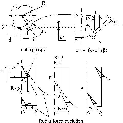
For a given angle, the generating point is in P at a
distance z of the spindle nose considered as a housing.
After a small rotation of the plain milling cutter, the gen-
erating point is in P at a distance z (Fig. 1). This
explains the variation of the radial forces and of the
tool deformations.
An elementary cutting edge placed at point Q, which
is in the workpiece material, cuts an elementary chip
section by applying an elementary force dF. At each
point P, the resulting deformation is the sum of the
elementary deformations caused by the engagement of
all the elementary lengths constituting the cutting edges
simultaneously engaged in the workpiece material. Fig.
Fig. 1. Evolution of the generating point of a tool.
2

Fig. 2. Force along a cutting edge according to the cutter angular
position.
2 represents the evolution of radial force per unit of
length along a helicoid developed prole on the
machined surface. a is the total tool engagement angle
in the workpiece material. Each point Q is characterized
by the angular position b and by its distance z to the
spindle nose.
The variation of the radial forces and that of the dis-
tances from point P to the presumed housing along a
machined section makes it possible to qualitatively
understand that the resulting deformation of the section
is not linear.
Fig. 3. Tool deformation.
2.2. Denition of the deformation model
The calculation of the cutting pressures is approached
by making use again of the Kline and DeVors model
[16]. We hence propose a force model based on the
decomposition of the tool into elementary discs the
thickness dz of which is considered as constant. Each
elementary force applied in each point Q of the cutting
edge in catch considered is decomposed into a tangential
component dFt and a radial component dFr:
dFr Kr.ep.dz Kr
o
.(fz.sin(b)).dz.(fz.sin(b))
0.3
dFt Kt.ep.dz Kt
o
.(fz.sin(b)).dz.(fz.sin(b))
0.3
. (1)
Specic cutting pressures Kr and Kt are supposed to
answer the following model:
Kr Kr
0
.ep
0.3
and Kt Kt
0
.ep
0.3
(2)
where ep is the depth of cut given by ep fz.sin(b).
This model was many times validated in the context
of turning, coefcient 0.3 appearing as a rather
stable constant.
The geometrical variations of the machined surface
are mainly due to the plain milling cutter deformation
in the normal plane to the surface. Only the component
dN of this cutting force interests us.
dN(b) dFr(b).cos(b) dFt(b).sin(b). (3)
We consider that the tool is a xed beam of constant
moment of inertia I
gz
, that is the case when the tool used
has a teeth number multiple of 4. The resulting defor-
mation dy at point P from coordinate z, due to the radial
force dN applied to point Q is given by:
dy
1
E.I
gz
.dN(b).
冋冉
(zL(b))
3
3
.
(zL(b))
2
.L(b)
2
冊册
(4)
where L(b) (h × b)/(2p)ifQ belongs to the same
tooth as P, h being the helicoı¨dal pitch and E being the
Youngs modulus of the tool. The moment of inertia is
given by I
gz
p·d
4
eq
/64 with d
eq
m·2R, R being the
plain milling cutter radius and m an equivalence ratio
identied during a static test similar to the test presented
in Fig. 5. An error in the determination of I
gz
has no
inuence on the identication precision as this error is
made up for at the time of the matrix system resolution
leading to the specic cutting coefcients values Kr
0
and Kt
0.
The total theoretical deformation yth
i
at point P
i
is the
sum of the elementary deformations dy generated by all
the points Q of the cutting edges engaged simultaneously
in the workpiece material.
yth
i
N
t
k 1
(b a)
(b 0)
dy
ik
N
t
k 1
1
E.I
gz
(b a)
(b 0)
dmf
ik
(5)
where the bending moment dmf
ik
is given by:
3

dmf
ik
dN(b).
冉冉
(z
i
L(b)
ik
)
3
3
(6)
(z
i
L(b)
ik
)
2
.L(b)
ik
2
冊冊
where i is the index of point P
i
along the studied line,
k is the number of the considered cutting edges and N
t
is the number of the teeth of the plain milling cutter.
The engagement angle a, useful for the integral calcu-
lation Eq. (5) depends on the cutting edge and on the
tool orientation. During this study, a basic model was
used by considering that the angle a is constant and cal-
culable for a radial engagement er given by a
acos((Rer)/R). We then noted rather signicant dif-
ferences between measurements and the estimates of
variations of the surface machined. We observed that
under effect of the the tool deformations, the maximum
engagement angle a considerably decreases. It was thus
necessary to set up a process to take the deformation in
the engagement angles calculation into account. Section
4 will specically detail this point.
Ultimately, the approach proposed in this article
extends the Kline and DeVors model [16] to the taking
into account of great axial engagements. The integral
relates to the deformation due to each elementary cutting
edge length whereas, in the original model, the integral
relates to the forces, the resultant forces being used to
calculate the deformation.
3. Identification procedure
3.1. Introduction
The determination of the force model coefcients is
a signicant stage for the prediction of the machining
defects. The estimate of these parameters classically
requires the realization of a signicant campaign of tests
during which the cutting pressures are generally meas-
ured with dynamometers [1824]. These experimental
data are then treated by an optimization method and lead
to the determination of the coefcients. The results
obtained always depend on the conditions of realization
of the tests and on the hypotheses of calculation set up.
The most current identication strategies concern the
direct measurement of characteristic components of the
cutting process for a tool-workpiece couple (Kr
0
, Kt
0
characterized) for given conditions. The measurement of
the force is difcult in an industrial cycle, because it
requires the maintainance of a cutting force turntable, its
central processing unit and a very qualied technician.
The examination is also rather delicate because there are
generally several teeth in catch. After that, it is necessary
to associate a tool deection model to the phenomenon
resulting from the presumed cutting forces.
To dene a protocol of identication answering the
industrial constraints, we use an indirect measurement
by quantifying the tool deection with the measurement
of the machined surface. The opposite problem is then
solved by comparing the theoretical deformation of the
tool with the deformation of the machined surface.
In this context, Landon and al. propose the machining
and the measurement of a master part gathering charac-
teristic machinings from which we can infer a law gov-
erning the machining defects [25]. The approach pro-
posed can be applied to all the types of machining and
is not based on a theoritical force model.
3.2. Principles of the procedure
To make the identication procedure easily reproduc-
ible industrially while reducing uncertainties related to
its implementation and its interpretation, a part should
be dened that allows to characterize a tool workpiece
couple on a given machine in stabilized mode.
3.2.1. Principles of the test selected
Taking the constraints previously evoked into account,
we dene a test protocol based on the ank milling in
concordance of a simple plane which is realizable on
any milling machine. To vary the depth of cut of 0.5 up
to 3 mm, the raw part has a specic form mainly consti-
tuted of a tilted plane (Fig. 4) and of surfaces dedicated
to the realization of references to facilitate measure-
ments.
The raw part is divided into four zones:
In the identication zone, the raw surface is a tilted
plane giving a depth of cut variation which is included
between 0.5 and 3 mm
The reference zones which require two narrow bands
Fig. 4. Specications of the raw part.
4

with a small depth of cut of 0.3 mm in order to limit
the cutting forces and the tool deections
A lateral slot that lets the tool end out of the work-
piece material.
In order to isolate the inuence of the tool deection
on the part defect, the tool end is left free to avoid the
disturbances caused by a parasitic friction of the tool
end.
3.2.2. Experimental validation of the assumptions
To obtain an experimental model representing the cut-
ting process as precisely as possible, the following
hypotheses are posed:
1. The part is very rigid and rmly taken in on the
part holder.
2. The part holder is very rigid.
3. The tool is considered as a xed beam.
4. The spindle of the machine unit is considered as a
rigid body.
To quantify the spindle deformation, a force of the
same order of magnitude (maximum 150 N) as the cur-
rent cutting force is applied on a very rigid test holder,
using a dynamometric ring. The induced deection is
obtained using two comparators for one point of load
(Fig. 5). The deviation of the spindle axis on the level
of the tool end is about 6 µm, which is negligible com-
pared to the observed variations on the part. In static,
the spindle can thus be regarded as a rigid bogy. The
point A, located near the spindle nose, is retained as the
presumed housing point.
To analyze the rigidity of the machine, a comparator
is xed on the spindle casing during the preceding
Fig. 5. Validation of the static rigidity of the machine.
identication test to measure the displacements of the
machine table compared to the spindle. The maximum
deformation noted is lower than 15 µm and will be neg-
lected too.
We nally consider that the dynamics of the machine
spindles does not disturb machining, because the
machined surface is a simple plane which is milled at
constant feedrate with a long stabilization and acceler-
ation distance before machining the central part
(section 3).
3.2.3. Principles of measurement
From an operational point of view, the identication
consists in machining the test part and measuring the
defects of the machined surface. These measurements
make it possible to establish a surface statement of the
deformations. This statement gives the actual value of
the deformation at each point of a measurement grid
posed on the machined surface. The step of the grid is
of 1 mm.
To measure the defects of the test part correctly, a
reference mark was conceived on the basis of reference
surfaces (Fig. 6). This reference mark is built by
bypassing the part with the tested tool by taking a weak
depth of cut of 0.3 mm on an axial engagement of 5
mm. It thus allows for an effective registration between
the reference mark part and the reference mark of the
CMM machine. This type of machining allows the con-
struction of reference surfaces while being freed from
the gauge and tool deection defects. The two zones
with low depth of cut located at the level of the part
ends are used to validate the registration of the measured
points cloud.
Within the framework of this article, the part test was
machined under the following conditions:
HSS tool whose diameter is 20 mm and whose active
length is 88 mm
Fig. 6. Reference mark useful for measurement.
5

Citations
More filters
Journal ArticleDOI
TL;DR: In this paper, a unified approach to identify the cutting force coefficients together with the cutter runout parameters for general end mills such as cylindrical, ball, bull nose ones, etc.
Abstract: This paper aims at developing a unified approach to identify the cutting force coefficients together with the cutter runout parameters for general end mills such as cylindrical, ball, bull nose ones, etc. The cutting forces that are modeled using the instantaneous cutting force coefficients are analyzed and separated into two terms: a nominal component independent of the runout and a perturbation component induced by the runout. The nominal component enables the calibration of the instantaneous cutting force coefficients whereas the runout parameters are determined from the perturbation component. The validity of the present method is demonstrated with simulation and experimented data.

131 citations


Cites methods from "Deviation of a machined surface in ..."

  • ...Kline et al. [1] proposed a calibration model of the cutting force coefficients using the average cutting forces measured whereas Larue and Anselmetti [2] developed a numerical cylindrical end milling force model using the cutter deflection measured....

    [...]

  • ...[1] proposed a calibration model of the cutting force coefficients using the average cutting forces measured whereas Larue and Anselmetti [2] developed a numerical cylindrical end milling force model using the cutter deflection measured....

    [...]

Journal ArticleDOI
TL;DR: In this article, a generic and improved model is introduced to simultaneously predict the conventional cutting forces along with 3D surface topography during side milling operation, incorporating the effects of tool runout, tool deflection, system dynamics, flank face wear, and the tool tilting on the surface roughness.
Abstract: During the milling operation, the cutting forces will induce vibration on the cutting tool, the workpiece, and the fixtures, which will affect the surface integrity of the final part and consequently the product's quality. In this paper, a generic and improved model is introduced to simultaneously predict the conventional cutting forces along with 3D surface topography during side milling operation. The model incorporates the effects of tool runout, tool deflection, system dynamics, flank face wear, and the tool tilting on the surface roughness. An improved technique to calculate the instantaneous chip thickness is also presented. The model predictions on cutting forces and surface roughness and topography agreed well with experimental results.

115 citations

Journal ArticleDOI
TL;DR: In this article, the authors developed efficient strategies for controlling the force-induced surface dimensional errors in peripheral milling of thin-walled structures, where the focus was on how to select the feed per tooth and depth of cut simultaneously for tolerance specification and maximization of the feed each tooth simultaneously.
Abstract: This paper aims at developing efficient strategies for controlling the force-induced surface dimensional errors in peripheral milling of thin-walled structures. Emphasis is put on how to select the feed per tooth and depth of cut simultaneously for tolerance specification and maximization of the feed per tooth simultaneously. Three methods are presented. The first one proceeds by optimally selecting the maximum feed per tooth without tolerance violation. The second one is to find the appropriate cutting parameters by solving a linear programming problem. To show the efficiency of the first two methods, the third one, i.e. the so-called mirror error compensation method taken from references, is also addressed for comparison. Mechanistic model for cutting force estimation, cantilever beam model for cutter deflection estimation and finite element method for workpiece deflection estimation are used in all three methods. Besides, improvements on the calculation scheme of the surface dimensional error have been made and both numerical and experimental results are adopted for verification.

97 citations


Cites methods from "Deviation of a machined surface in ..."

  • ...Kline [6], Larue [7], Budak [8], Shirase [9], Ryu [10] and Paksiri [11] used the cutter deflection to predict the surface dimensional errors whereas Ratchev et al. [5,12,13] used the workpiece deflections to calculate surface dimensional error of milled flexible component....

    [...]

  • ...Kline [6], Larue [7], Budak [8], Shirase [9], Ryu [10] and Paksiri [11] used the cutter deflection to predict the surface dimensional errors whereas Ratchev et al....

    [...]

Journal ArticleDOI
TL;DR: In this paper, the Nelder-Mead simplex method was used to calibrate the instantaneous cutting force coefficients and the cutter runout parameters for peripheral milling, and the results show that they are efficient and reliable.
Abstract: In this paper, new procedures are proposed to calibrate the instantaneous cutting force coefficients and the cutter runout parameters for peripheral milling. By combining with optimization algorithm, i.e., the Nelder–Mead simplex method, detailed calibration schemes are derived for a mechanistic cutting force model in which the cutting force coefficients are described as the exponential functions of the instantaneous uncut chip thickness. Three different cutter runout models are considered in the calculation of instantaneous uncut chip thickness. Only one or two tests are required to perform the calibration. Experimental verifications are also conducted to validate the proposed procedures, and the results show that they are efficient and reliable. To see the effect of different runout models on milling process, comparisons among the predicted results under a wide range of cutting parameters are made to study the consistency and limitations of different models. It is found that the radial cutter runout model is a recommendable one for cutting force modelling.

92 citations

Journal ArticleDOI
TL;DR: In this article, the authors defined a mechanical workspace for a tricept structure with telescopic legs for grooving and drilling operations, and a simulation showed that leg deflection gives rise to defects of the machined entity which are evaluated with respect to tool position and orientation.
Abstract: This paper deals with parallel kinematics machine (PKM) applications for high speed machining. PKM behaviour is anisotropic, so structural deflection due to cutting loads generates different defects in the machined part, according to tool position and orientation in the workspace. The aim of the present study is the definition of a mechanical workspace where the part is machined to a specified quality level. Models of the machine tool structure, the load generated by the cutting phenomena and the machined surface are used to determine this workspace and are applied to a tricept structure with telescopic legs for grooving and drilling operations. A simulation shows that leg deflection gives rise to defects of the machined entity which are evaluated with respect to tool position and orientation. Finally, a mechanical workspace is defined for a drilling process using a tricept structure machine tool.

84 citations

References
More filters
Journal ArticleDOI
TL;DR: In this article, a new method for the analytical prediction of stability lobes in milling is presented, which requires transfer functions of the structure at the cutter -workpiece contact zone, static cutting force coefficients, radial immersion and the number of teeth on the cutter.

1,632 citations

Journal ArticleDOI
TL;DR: In this paper, the authors compared the mechanistic and unified mechanics of cutting approaches to the prediction of forces in milling operations and showed that the milling force coefficients for all force components and cutter geometrical designs can be predicted from an orthogonal cutting data base and the generic oblique cutting analysis for use in the predictive mechanistic milling models.
Abstract: The mechanistic and unified mechanics of cutting approaches to the prediction of forces in milling operations are briefly described and compared. The mechanistic approach is shown to depend on milling force coefficients determined from milling tests for each cutter geometry. By contrast the unified mechanics of cutting approach relies on an experimentally determined orthogonal cutting data base (i.e., shear angle, friction coefficient and shear stress), incorporating the tool geometrical variables, and milling models based on a generic oblique cutting analysis. It is shown that the milling force coefficients for all force components and cutter geometrical designs can be predicted from an orthogonal cutting data base and the generic oblique cutting analysis for use in the predictive mechanistic milling models. This method eliminates the need for the experimental calibration of each milling cutter geometry for the mechanistic approach to force prediction and can be applied to more complex cutter designs. This method of milling force coefficient prediction has been experimentally verified when milling Ti 6 Al 4 V titanium alloy for a range of chatter, eccentricity and run-out free cutting conditions and cutter geometrical specifications.

640 citations

Journal ArticleDOI
TL;DR: In this article, the authors present a mechanistic model for the force system in end milling, which is based on chip load, cut geometry, and the relationship between cutting forces and chip load.

477 citations

Journal ArticleDOI
TL;DR: In this paper, the authors use peak-to-peak (PTP) diagrams for the evaluation of the results of multiple runs of a time-domain simulation of a ding process, which summarize the amplitudes of the forces, deflections, or surface finishes resulting from a large number of simulations through a range of axial depths of cut and spindle speed.

218 citations

Journal ArticleDOI
J. Tlusty1

215 citations

Frequently Asked Questions (12)
Q1. What contributions have the authors mentioned in the paper "Deviation of a machined surface in flank milling" ?

This article present the results of an identification procedure of the coefficients of a force model for a given tool workpiece couple for the prediction of the defects of the tool during the cutting. The calibration method proposed meets a double aim: to define an experimental protocol that takes the industrial constraints of time and cost into account and to work out a protocol which minimizes uncertainties likely to alter the interpretation of the results ( environmental, software or mechanical uncertainties ). 

The geometrical variations of the machined surface are mainly due to the plain milling cutter deformation in the normal plane to the surface. 

In order to isolate the influence of the tool deflection on the part defect, the tool end is left free to avoid the disturbances caused by a parasitic friction of the tool end. 

The measurement of the force is difficult in an industrial cycle, because it requires the maintainance of a cutting force turntable, its central processing unit and a very qualified technician. 

In order to determine the pressure coefficients, the authors use a method of least squares which minimizes the sum of the squared differences between the deformation measured and the one calculated theoretically thanks to the model previously described, for each point of the grid which is posed on the surface to machine. 

The numerous existing force models can be classified into two modeling levels: ‘microscopic modelisation’ studies the interaction between the tool and the workpiece material by using thermomechanical behavior lawsand ‘global modelisation’ considers the force resulting from the contact between the tool and the part along the cutting edges in catch. 

To quantify the spindle deformation, a force of the same order of magnitude (maximum 150 N) as the current cutting force is applied on a very rigid test holder, using a dynamometric ring. 

Flank milling of free surfaces traditionally implies the generation of machining tool paths that will ensure an optimal laying of the presumed rigid tool on the surface∗ 

The identification procedure of a tool workpiece couple proposed in this article is a procedure which takes the industrial constraints of time and cost into account. 

The deviation of the spindle axis on the level of the tool end is about 6 µm, which is negligible compared to the observed variations on the part. 

In flank milling with long tools, the geometrical errors generated by the tool deflection during the cutting process can be very significant. 

The authors thus obtain a 2p.tmaxi /h.The entrance point of a cutting edge in the workpiece material is also calculated by intersection between the parametric curve previously defined and the sides of the workpiece faces.