scispace - formally typeset
Search or ask a question
Journal ArticleDOI

Direct finite element computation of non-linear modal coupling coefficients for reduced-order shell models

TL;DR: In this paper, the authors proposed a method for computing modal coupling coefficients for thin shells vibrating at large amplitude and discretized by a finite element (FE) procedure. But their method is not suitable for the case of a single oscillator.
Abstract: We propose a direct method for computing modal coupling coefficients--due to geometrically nonlinear effects--for thin shells vibrating at large amplitude and discretized by a finite element (FE) procedure. These coupling coefficients arise when considering a discrete expansion of the unknown displacement onto the eigenmodes of the linear operator. The evolution problem is thus projected onto the eigenmodes basis and expressed as an assembly of oscillators with quadratic and cubic nonlinearities. The nonlinear coupling coefficients are directly derived from the FE formulation, with specificities pertaining to the shell elements considered, namely, here elements of the "Mixed Interpolation of Tensorial Components" family. Therefore, the computation of coupling coefficients, combined with an adequate selection of the significant eigenmodes, allows the derivation of effective reduced-order models for computing--with a continuation procedure --the stable and unstable vibratory states of any vibrating shell, up to large amplitudes. The procedure is illustrated on a hyperbolic paraboloid panel. Bifurcation diagrams in free and forced vibrations are obtained. Comparisons with direct time simulations of the full FE model are given. Finally, the computed coefficients are used for a maximal reduction based on asymptotic nonlinear normal modes, and we find that the most important part of the dynamics can be predicted with a single oscillator equation.

Summary (2 min read)

1 Introduction

  • Thin shells vibrating at large amplitude can exhibit complex dynamics.
  • In conjunction with a numerical continuation method [3,4], or perturbation analytical methods [5], one is able to obtain complete bifurcation diagrams for free vibrations and forced responses of thin structures.
  • Unfortunately, this strategy is restricted to simple geometries, for which ad-hoc functional bases made of simple – often analytical – functions can be constructed, ensuring convergence for a small number of modes.
  • From the computation of the residual, and via algebraic manipulations, nonlinear coupling coefficients can be evaluated.
  • The authors propose and implement a direct method with application to FE shells discretized with general shell elements of the MITC family (Mixed Interpolation of Tensorial Components) [18].

2 Direct computation of nonlinear stiffness

  • This section gives the analytical and implementation details for the direct computation of the nonlinear coupling coefficients describing the geometrical nonlinearity of the shell.
  • Other basis functions could have been used for the Galerkin projection, such as POD modes (Proper Orthogonal Decomposition, see for instance [20– 22]).
  • As is well-known, shell finite elements suffer from very serious numerical pathologies when directly discretizing standard kinematical assumptions – namely, when using so-called “displacements-based elements”– see [18] and references therein.
  • Therefore, the authors substitute for the above displacement-based strain vector the modified expression ˜ e = [err ess ers esr Irerz Irezr Isesz Isezs] t, Ir and Is denoting the interpolation operators, and likewise for the linear variations.
  • Similar results up to machine precision have been obtained, hence validating the direct numerical computation of non-linear coefficients.

3 Application : a hyperbolic paraboloid panel

  • The general methodology given in the previous section is now applied with a practical test case given by a shallow hyperbolic paraboloid panel.
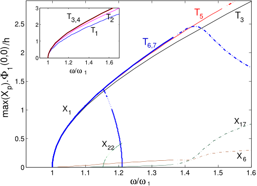
  • The first truncation T1 shown in the insert of Fig. 6 contains only the fundamental mode, and displays a hardening behavior.
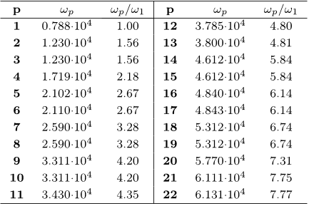
  • The transverse modes, with the lowest eigenfrequencies, are given for p=1 to 22 in Table 2.
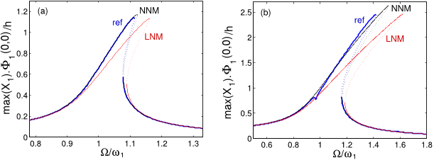
  • In the case of forced and damped vibrations, the amplitude responses predicted by the ROM and shown in Fig. 7 can be compared to direct simulations on the full FE model, so as to ascertain the quality of the ROM and its ability to predict the correct amplitude values.
  • This might be ascribed to the fact that the 3:1 resonance is activated when the nonlinear frequencies share the perfect 3:1 relationship, and the complete model may feature a slight difference in the evolution of the higher frequencies versus vibration amplitude.

4 Conclusion

  • A direct method has been presented for computing the nonlinear stiffness in geometric nonlinear vibration of thin shells discretized by finite elements.
  • These formulas have been implemented in a FE code within the framework of MITC shell elements.
  • The method gives fast and reliable computations for these coefficients, the accuracy of which has been validated by comparison with an indirect method.
  • The computation of these coefficients can be used for deriving reducedorder models of great accuracy, allowing for precise prediction of nonlinear vibration characteristics of shell models.
  • Such studies will also allow a more extensive assessment of the criterion used in the present paper to select the important modes in the ROM, which can lead to an automatized selection procedure.

Did you find this useful? Give us your feedback

Figures (12)

Content maybe subject to copyright    Report

HAL Id: hal-00955582
https://hal.inria.fr/hal-00955582
Submitted on 4 Mar 2014
HAL is a multi-disciplinary open access
archive for the deposit and dissemination of sci-
entic research documents, whether they are pub-
lished or not. The documents may come from
teaching and research institutions in France or
abroad, or from public or private research centers.
L’archive ouverte pluridisciplinaire HAL, est
destinée au dépôt et à la diusion de documents
scientiques de niveau recherche, publiés ou non,
émanant des établissements d’enseignement et de
recherche français ou étrangers, des laboratoires
publics ou privés.
Direct nite element computation of non-linear modal
coupling coecients for reduced-order shell models
Cyril Touzé, Marina Vidrascu, Dominique Chapelle
To cite this version:
Cyril Touzé, Marina Vidrascu, Dominique Chapelle. Direct nite element computation of non-linear
modal coupling coecients for reduced-order shell models. Computational Mechanics, Springer Verlag,
2014, 54, pp.567-580. �10.1007/s00466-014-1006-4�. �hal-00955582�

Noname manuscript No.
(will be inserted by the edit or )
Direct finite element computation
of non-linear modal coupling coefficients
for reduced-order shell models
C. Touz´e · M. Vidrascu · D . Chapelle
Computational Mechanics, DOI:10.1007/s00466-014-1006-4
Abstract We propose a direct metho d for computing modal coupling coef-
ficients due to geometrically nonlinear effects for thin shells vibrating at
large amplitude and discretized by a finite element (FE) p r ocedure. These
coupling coefficients arise when consi de ri n g a discrete e xpan s ion of the un-
known displacement onto the ei gen modes of the linear operator. The evolu-
tion problem is thus projected onto the eigenmodes basis and expressed as an
assembly of oscillators with quadratic and cubic nonlinearities. The nonlinear
coupling coefficients are directly derived from the finite element formulation,
with specificities per t ain i ng to the shel l elements considered, namely, here ele-
ments of the “Mixed Interpolati on of Tensorial Components” family (MI TC) .
Therefore, the computati on of coupling coefficients, combined with an ade-
quate selection of the significant eigenmodes, allows the derivation of effective
reduced-order models for compu t in g with a continuation procedure the sta-
ble and unstable vibratory states of any vibrating shell, up to large amplitudes.
The procedure is illustr at ed on a hyperbolic paraboloid panel. Bifurcation di-
agrams in free and forced vibrat ion s are obtained. Comparisons with direct
time simulations of the full FE model are given. Finally, t he computed coeffi-
C. Touz´e
Unit´e de ecanique (UME),
ENSTA-ParisTech, 828 Boulevard des mar´echaux,
91762 Palaiseau Cedex, France
Tel.: +33-1-69-31-97-34
E-mail: cyril.touze@ensta-paristech.fr
M. Vidrascu
Inria/Reo and LJLL UMR 7958 UPMC,
Rocque nc ourt, B.P. 105, 78153 Le Chesnay, France
E-mail: marina.vidrascu@inria.fr
D. Chapelle
Inria/MΞDISIM, 1 rue Honor´e d’Estienne d’Orves,
Campus de l’Ecole Polytechnique, 91120 Palaiseau, France
E-mail: dominique.chapelle@inria.fr

2 C. Touz´e et al.
cients are used for a maximal reduction based on asymptotic nonlinear normal
modes ( NNM s) , an d we find that the most important part of the dynamics
can be predicted with a single oscillator equation.
Keywords geometric n onl i ne ar ity · finite elements · MITC elements ·
stiffness evaluation · bifurcation diagram · reduced-ord er models
1 Intro d u ct ion
Thin shells vibrating at large amplitude can exhibit complex dynamics. These
geometrically nonlinear behaviors occur as soon as the vibration amplitude is
of the order of the thickness, and may induce various nonlinear effects such
as jumps, instabilities, quasi-periodic or chaotic vibrat ion s [1, 2]. In turn, this
may lead to undesirable vib rat i on patterns that can have detrimental effects
on the usual predicted behavior of numerous engineering systems, such as
sudden increase in vibration amplitudes, fatigue of components, etc.. In or-
der to have a significant understanding of the possible nonlinear behaviors
of a given structure, the computation of a complete bifurcation diagram is
key, as it gives access to all th e solution branches (stable and unstable) un-
der variations of some selected control parameters. For that purpose, direct
numerical integration generally appears as cumbersome and inappropriate, as
unstable states are not accessible to the computation. Moreover, computing
all t h e solution branches by successive runs, given variabl e initial conditions,
is so ti m e-c ons um in g that the method is usually not considered.
In this context, reduced-order models (ROMs) are gen er al l y much better
adapted. In conjunction with a numerical continuation method [3,4], or per-
turbation analytical methods [5], one is ab le to obtain complete bifurcation
diagrams for free vibrations and forced respon se s of thin structures. In the last
years, many applications have been pursued usi ng this methodology, i n order
to compute frequency response curves of thin structur es harmonically forced in
the vicinity of one of its eigenmodes, see e.g. [5,2,6–9]. In most contributions,
the Partial Differential Equations (PDEs) of motion for a given shell model
following e.g. von arm´an assumptions, or Donnel l shallow-shell theory, see
e.g. [10] is discretized by using the eigenmodes of the linear operator, or a
given ad-hoc func t i onal basis that satisfi es the boundary conditions. Applying
a Galerkin pro c ed ur e, the problem is then transformed into a dynamical sys-
tem by conserving the important modes, for which continuation methods can
thus be applied. Unfortunately, this strategy is restricted to simple geometries,
for which ad-hoc functional bases made of simple often analytical func-
tions can be constructed, ensuring convergence for a smal l number of modes.
For a general shell geometry, finding such a specific discretization method is
much more di ffic ul t , see e.g. [11] for a proposed approach based on so-called
R-functions.
For complex geometries the most common framework consists in using
the versatility of finite-elements (FE) procedures. However, at the time being,

Title Suppressed Due to Excessive Length 3
there exists no contribution on reduce d- orde r models based on shell finite el-
ements for predicting bifurcation diagrams by a continuation method. More
precisely, first attempts toward this general objecti ve can be found in [12] for
beam-like structures, and in [13,14] for rectangular plat es. The present paper
aims at proposing a complete strategy specifically adapted to tackle the most
general case of thin shells. The main difficulty resides in the computation of the
ROM from th e FE discretized shell. A simple strategy that is used in th is con-
tribution consist s in uti l iz i ng the e ige nm odes basis in the construction process
of the ROM. The dynamical problem, expressed onto the linear eigenmodes, is
represented by an assembly of oscillators with qu ad rat i c and cubic nonlinear-
ities, arising from the geometricall y nonlinear terms. Within that framework,
numerous nonlinear coupling coefficients appear in the dynamical system, and
one needs to evaluate these coefficient s in order to build the ROM.
Indirect d et er mi n at i on of these nonlinear coupling coefficients has already
been proposed. Muravyov [15], then Mignolet and Soize [16] used a so-called
STEP method (STiffness Evaluation Procedure) for that purpose. The ide a
is to prescribe in the structural model numerous selected static deformations,
taken from one of the eigenmodes or a combination thereof. From the c om-
putation of the residual, and via algebraic manipulations, nonlinear coupling
coefficients can be evalu at ed . A review of the computational schemes, as well
as their applications to solve numerous engineering problems involving for ex-
ample random vibrati on s, is given in [17]. The main advantage of the STEP
method is that one can use any commercial finite element software, as there
is no need to compute specific finite element quantities, and only standard
computations with specific post-processing allow to derive the desired coeffi-
cients. The drawback of this indirect method is that numerous well-selected
combinations of static deformations must be considered; moreover, the method
requires prescribing an appropriate amplitude for the static deflections.
In this contribution, we propose and implement a direct method with ap-
plication to FE shel ls discretized with general shell elements of the MITC
family (Mixed Interpolation of Tensorial Components) [ 18] . First an analyti-
cal expression of t h e nonlinear coupling coefficients is derived from the internal
potent i al energy. The FE procedure an d implementation details are then given.
Next, the method is applied to a clamped hyperbolic paraboloid panel. In this
case, the detailed derivation of ROMs is explained, and bifurcation diagrams
in free and f orc ed vibr at i ons are given.
2 D ir ect computation of nonlinear stiffness
This section gives the analy t i cal and implementation details for the direct
computation of the nonlinear coupling coefficients describing the geometrical
nonlinearity of the shell. The l i n ear modes basis is used to discretize the FE
problem, and specificities related to the use of the chosen shell elements are
then thoroughly explained so as to highlight the practical i m pl em entation of
the calculation in a given shell FE code.

4 C. Touz´e et al.
2.1 Formulation
This section is devoted to the analytical expressions of the nonlinear coupling
coefficients. Geometric nonlinearity is assumed, which means th at the mate-
rial has a linear elastic behavior, but t he shell can undergo large amplitude
motions. In this context, the nonlinearit i es can be directly derived from the
variations of internal elastic energy δW
int
, w hi ch read
δW
int
=
Z
Σ
: δe, (1)
where Σ is the second Piola-Kirchhoff stress te ns or and e the Green-Lagrange
strain tensor. The strain-displacement relationship is
e =
1
2
+
t
+
t
.
y
, (2)
where y stands for the displac eme nt. For simplicity, l e t us denote by ε the
linear part of the s t rai n -d i sp lac eme nt rel ati on sh i p
ε =
1
2
+
t
y
, (3)
and e
(2)
the quadratic part
e
(2)
=
1
2
t
y
. y
. (4)
A li n ear elas t i c and isotropic mater i al is assumed, so that we have
Σ
= H : e, (5)
where H stands for the constitutive tensor associated with a Saint-Venant-
Kirchhoff material, namely, Hooke’s law.
Then we have
δW
int
=
Z
ε
+ e
(2)
: H
:
δε + δe
(2)
. (6)
From this last equation, one can identify the linear, quadrat i c and cubic terms
(as functions of the displacement), which are denoted respectively by δW
1
,
δW
2
et δW
3
δW
1
=
Z
ε
: H : δε, (7)
δW
2
=
Z
e
(2)
: H
: δε + ε : H : δe
(2)
, (8)
δW
3
=
Z
e
(2)
: H
: δe
(2)
. (9)

Citations
More filters
Journal ArticleDOI
TL;DR: This article proposes an efficient experimental strategy to measure the backbone curve of a particular nonlinear mode and uses it to identify the free parameters of the reduced order model and validate the procedure by comparison to available theoretical models as well as to other experimental identification methods.

56 citations


Cites background from "Direct finite element computation o..."

  • ...We also restrict our attention to geometrically nonlinear structures, for which fnl(x) is a quadratic and cubic polynomial function of x [22, 21, 23]....

    [...]

Journal ArticleDOI
TL;DR: In this article, a review of nonlinear methods for model order reduction in structures with geometric nonlinearity is presented, with a special emphasis on the techniques based on invariant manifold theory.
Abstract: This paper aims at reviewing nonlinear methods for model order reduction in structures with geometric nonlinearity, with a special emphasis on the techniques based on invariant manifold theory. Nonlinear methods differ from linear-based techniques by their use of a nonlinear mapping instead of adding new vectors to enlarge the projection basis. Invariant manifolds have been first introduced in vibration theory within the context of nonlinear normal modes and have been initially computed from the modal basis, using either a graph representation or a normal form approach to compute mappings and reduced dynamics. These developments are first recalled following a historical perspective, where the main applications were first oriented toward structural models that can be expressed thanks to partial differential equations. They are then replaced in the more general context of the parametrisation of invariant manifold that allows unifying the approaches. Then, the specific case of structures discretised with the finite element method is addressed. Implicit condensation, giving rise to a projection onto a stress manifold, and modal derivatives, used in the framework of the quadratic manifold, are first reviewed. Finally, recent developments allowing direct computation of reduced-order models relying on invariant manifolds theory are detailed. Applicative examples are shown and the extension of the methods to deal with further complications are reviewed. Finally, open problems and future directions are highlighted.

54 citations

Journal ArticleDOI
TL;DR: In this paper, a reduced-order model (ROM) is obtained by an expansion onto the eigenmode basis of the associated linearized problem, including transverse and in-plane modes.
Abstract: This paper presents a general methodology to compute nonlinear frequency responses of flat structures subjected to large amplitude transverse vibrations, within a finite element context. A reduced-order model (ROM)is obtained by an expansion onto the eigenmode basis of the associated linearized problem, including transverse and in-plane modes. The coefficients of the nonlinear terms of the ROM are computed thanks to a non-intrusive method, using any existing nonlinear finite element code. The direct comparison to analytical models of beams and plates proves that a lot of coefficients can be neglected and that the in-plane motion can be condensed to the transverse motion, thus giving generic rules to simplify theROM. Then, a continuation technique, based on an asymptotic numerical method and the harmonic balance method, is used to compute the frequency response in free (nonlinear mode computation) or harmonically forced vibrations. The whole procedure is tested on a straight beam, a clamped circular plate and a free perforated plate for which some nonlinear modes are computed, including internal resonances. The convergence with harmonic numbers and oscillators is investigated. It shows that keeping a few of them is sufficient in a range of displacements corresponding to the order of the structure’s thickness, with a complexity of the simulated nonlinear phenomena that increase very fast with the number of harmonics and oscillators.

50 citations

Journal ArticleDOI
TL;DR: In this paper, the effects of both the thickness profile and the damping layer are investigated in order to improve the acoustic black hole effect (ABH) beam's damping properties.
Abstract: Acoustic Black Hole effect (ABH) is a passive vibration damping technique without added mass based on flexural waves properties in thin structures with variable thickness. A common implementation is a plate edge where the thickness is locally reduced with a power law profile and covered with a viscoelastic layer. The plate displacement in the small thickness region is large and easily exceeds the plate thickness. This is the origin of geometric nonlinearity which can generate couplings between linear eigenmodes of the structure and induce energy transfer between low and high frequency regimes. This phenomenon may be used to increase the efficiency of the ABH treatment in the low frequency regime where it is usually inefficient. An experimental investigation evidenced that usual ABH implementation gives rise to measurable geometric nonlinearity and typical nonlinear phenomena. In particular, strongly nonlinear regime and wave turbulence are reported. The nonlinear ABH beam is then modeled as a von Karman plate with variable thickness. The model is solved numerically by using a modal method combined with an energy-conserving time integration scheme. The effects of both the thickness profile and the damping layer are then investigated in order to improve the damping properties of an ABH beam. It is found that a compromise between the two effects can lead to an important gain of efficiency in the low frequency range.

49 citations

Journal ArticleDOI
TL;DR: The direct computation of the third-order normal form for a geometrically nonlinear structure discretised with the finite element (FE) method, is detailed, allowing to define a nonlinear mapping in order to derive accurate reduced-order models (ROM) relying on invariant manifold theory.

48 citations


Cites methods from "Direct finite element computation o..."

  • ...Application of these methods to finite-element (FE) structures with geometric distributed nonlinearity, remains however scarce [26,32,33]....

    [...]

  • ...elasticity, it implies that only quadratic and cubic polynomial terms have to be taken into account [3,57,32,33], they are expressed thanks to the terms G(X,X) and H(X,X,X), using a functional notation for the quadratic and cubic terms with coefficients gathered in third-order tensor G and fourth-order tensor H....

    [...]

References
More filters
Book
26 Jun 1995
TL;DR: The Finite Element Method as mentioned in this paper is a method for linear analysis in solid and structural mechanics, and it has been used in many applications, such as heat transfer, field problems, and Incompressible Fluid Flows.
Abstract: 1. An Introduction to the Use of Finite Element Procedures. 2. Vectors, Matrices and Tensors. 3. Some Basic Concepts of Engineering Analysis and an Introduction to the Finite Element Methods. 4. Formulation of the Finite Element Method -- Linear Analysis in Solid and Structural Mechanics. 5. Formulation and Calculation of Isoparametric Finite Element Matrices. 6. Finite Element Nonlinear Analysis in Solid and Structural Mechanics. 7. Finite Element Analysis of Heat Transfer, Field Problems, and Incompressible Fluid Flows. 8. Solution of Equilibrium Equations in State Analysis. 9. Solution of Equilibrium Equations in Dynamic Analysis. 10. Preliminaries to the Solution of Eigenproblems. 11. Solution Methods for Eigenproblems. 12. Implementation of the Finite Element Method. References. Index.

8,068 citations


"Direct finite element computation o..." refers methods in this paper

  • ...We consider general shell elements [23,18], hence discrete displacements are defined according to an isoparametric strategy as...

    [...]

Journal ArticleDOI
TL;DR: The Navier-Stokes equations are well-known to be a good model for turbulence as discussed by the authors, and the results of well over a century of increasingly sophisticated experiments are available at our disposal.
Abstract: It has often been remarked that turbulence is a subject of great scientific and technological importance, and yet one of the least understood (e.g. McComb 1990). To an outsider this may seem strange, since the basic physical laws of fluid mechanics are well established, an excellent mathematical model is available in the Navier-Stokes equations, and the results of well over a century of increasingly sophisticated experiments are at our disposal. One major difficulty, of course, is that the governing equations are nonlinear and little is known about their solutions at high Reynolds number, even in simple geometries. Even mathematical questions as basic as existence and uniqueness are unsettled in three spatial dimensions (cf Temam 1988). A second problem, more important from the physical viewpoint, is that experiments and the available mathematical evidence all indicate that turbulence involves the interaction of many degrees of freedom over broad ranges of spatial and temporal scales. One of the problems of turbulence is to derive this complex picture from the simple laws of mass and momentum balance enshrined in the NavierStokes equations. It was to this that Ruelle & Takens (1971) contributed with their suggestion that turbulence might be a manifestation in physical

3,721 citations

Book
02 Sep 2009
TL;DR: In this article, the authors present a model for symmetric integration of non-Canonical Hamiltonian systems and a model of symmetric Hamiltonian integration with symmetric integrators.
Abstract: Examples and Numerical Experiments.- Numerical Integrators.- Order Conditions, Trees and B-Series.- Conservation of First Integrals and Methods on Manifolds.- Symmetric Integration and Reversibility.- Symplectic Integration of Hamiltonian Systems.- Non-Canonical Hamiltonian Systems.- Structure-Preserving Implementation.- Backward Error Analysis and Structure Preservation.- Hamiltonian Perturbation Theory and Symplectic Integrators.- Reversible Perturbation Theory and Symmetric Integrators.- Dissipatively Perturbed Hamiltonian and Reversible Systems.- Oscillatory Differential Equations with Constant High Frequencies.- Oscillatory Differential Equations with Varying High Frequencies.- Dynamics of Multistep Methods.

3,587 citations


Additional excerpts

  • ...time-discretization following a Störmer-Verlet (or leap-frog) scheme [40]....

    [...]

Journal ArticleDOI
TL;DR: In this article, a general quadrilateral shell element for geometric and material nonlinear analysis is presented, which is formulated using three-dimensional continuum mechanics theory and it is applicable to the analysis of thin and thick shells.
Abstract: A new four‐node (non‐flat) general quadrilateral shell element for geometric and material non‐linear analysis is presented. The element is formulated using three‐dimensional continuum mechanics theory and it is applicable to the analysis of thin and thick shells. The formulation of the element and the solutions to various test and demonstrative example problems are presented and discussed.

1,187 citations


"Direct finite element computation o..." refers background in this paper

  • ...Instead, each strain component in the (r, s, z) coordinate system is re-interpolated within every element, according to a specific rule based on given points – called the “tying points” – at which the strains are exactly calculated [18,24]....

    [...]

Frequently Asked Questions (20)
Q1. What have the authors contributed in "Direct finite element computation of non-linear modal coupling coefficients for reduced-order shell models" ?

The authors propose a direct method for computing modal coupling coefficients – due to geometrically nonlinear effects – for thin shells vibrating at large amplitude and discretized by a finite element ( FE ) procedure. The evolution problem is thus projected onto the eigenmodes basis and expressed as an assembly of oscillators with quadratic and cubic nonlinearities. 

It also paves the way for further fine numerical studies of bifurcation diagrams for shells of arbitrary complex geometry. Such studies will also allow a more extensive assessment of the criterion used in the present paper to select the important modes in the ROM, which can lead to an automatized selection procedure. 

In order to have a significant understanding of the possible nonlinear behaviors of a given structure, the computation of a complete bifurcation diagram is key, as it gives access to all the solution branches (stable and unstable) under variations of some selected control parameters. 

In conjunction with a numerical continuation method [3,4], or perturbation analytical methods [5], one is able to obtain complete bifurcation diagrams for free vibrations and forced responses of thin structures. 

Analytical expressions of the nonlinear coupling coefficients have been expressed from the internal elastic energy by using a modal expansion for the displacement. 

The first physical effect that the reduced-order model must mandatorily capture is the coupling between bending and membrane motions. 

A converged ROM including 20 linear modes has been shown to predict with excellent accuracy the resonant response of a HP panel in the vicinity of its fundamental frequency. 

As peculiar nonlinear phenomena will be exhibited, a very good accuracy on all the numerical values is needed so as to ensure a good convergence of the reduced-order model. 

An internal resonance tongue has been found with mode 22, albeit it occurs in a very narrow interval, so that its effect on the global dynamics of the forceddamped system is likely to be negligible. 

the authors specifically select linear eigenmodes as a projection basis for the following two reasons:– it allows for a decoupling between linear components, – eigenmodes are easily computable in any standard FE code. 

The reduced-order model may be used for either direct time integration, or, as shown next, for computing by a continuation method the bifurcation diagram in the vicinity of a given dynamical state. 

This absence of stable periodic orbit is consistent with previous studies on the transition to turbulence for thin plates and shells, see e.g. [34–36], where it has been found that from vibration amplitudes of 2 to 4h (depending on the structure considered), no stable periodic solutions exist anymore, so that the dynamical solution is at least quasi-periodic. 

it has been emphasized in [36] that when the internal resonance occurs in a narrow interval as here observed, its influence on the frequency response in the forced-damped system is negligible. 

Concerning the M-modes, the mode labeled 224 is the first one in increasing frequency order that shows a strong coupling with the fundamental mode and thus will be key in the selection procedure explained in the next section. 

One observes that the hardening behavior is less pronounced, which reveals the effect of adding those modes in order to correctly reproduce the nonlinear vibrating behavior of the panel. 

The amplitude limit in the case presented here of the HP panel is found to converge to a value of 2.3h, as shown by the last two truncations which are superimposed, T6 and T7. 

This is because the authors need to deal with non-symmetric tensors for the computations of the nonlinear stiffness coefficients in (14)-(15), since the tensor ∇tΦi. 

For the full FE model, the maximum amplitude of the transverse displacement at the center is shown, whereas for the ROM the continuation software AUTO gives the maximum amplitude of each coordinate Xp, without their relative phases, so that one is not able to reconstruct precisely the complete transverse displacement by adding all modal coordinates according to Eq. (10). 

In order to compute the coefficients gpij and h p ijk consistently with the finite element procedure, the authors thus need to modify the components of the second-order tensors ∇tΦi. 

The convergence with this number of high-frequency modes is shown in the insert of Fig. 6, where only the fundamental B-mode is retained with an increasing number of M-modes.