scispace - formally typeset
Search or ask a question
Proceedings ArticleDOI

Distributed control in adaptive optics: Deformable mirror and turbulence modeling

28 Jun 2006-Proceedings of SPIE (International Society for Optics and Photonics)-Vol. 6272, pp 12
TL;DR: In this paper, a distributed framework is introduced in which each actuator has a separate processor that can communicate with a few direct neighbors, and the wavefront reconstruction step is fitted into the distributed framework such that the computational complexity for each processor increases only linearly with the telescope diameter.
Abstract: Future large optical telescopes require adaptive optics (AO) systems whose deformable mirrors (DM) have ever more degrees of freedom. This paper describes advances that are made in a project aimed to design a new AO system that is extendible to meet tomorrow's specifications. Advances on the mechanical design are reported in a companion paper [6272-75], whereas this paper discusses the controller design aspects. The numerical complexity of controller designs often used for AO scales with the fourth power in the diameter of the telescope's primary mirror. For future large telescopes this will undoubtedly become a critical aspect. This paper demonstrates the feasibility of solving this issue with a distributed controller design. A distributed framework will be introduced in which each actuator has a separate processor that can communicate with a few direct neighbors. First, the DM will be modeled and shown to be compatible with the framework. Then, adaptive turbulence models that fit the framework will be shown to adequately capture the spatio-temporal behavior of the atmospheric disturbance, constituting a first step towards a distributed optimal control. Finally, the wavefront reconstruction step is fitted into the distributed framework such that the computational complexity for each processor increases only linearly with the telescope diameter.

Summary (2 min read)

1. INTRODUCTION

  • Over the years, adaptive optics (AO) has grown from wild ideas to a proven technology that is indispensable for any large telescope.
  • Standard control approaches for AO consist of operations that typically scale with the number of actuators squared, which means that the total computational complexity of the controller increases with the telescope diameter to the fourth power.
  • Many results towards realizing this are already available,1,2 but few methods implemented for AO fully exploit all available wavefront information.
  • Advances in the design of the DM are discussed in,4 while this paper focusses on the controller design, for which a fully distributed control approach will be introduced.
  • 6–8 Often, the atmospheric disturbance is assumed to show a frozen flow characteristic, which makes it well predictable.

2. DISTRIBUTED CONTROL DESIGN FRAMEWORK

  • The distributed controller framework consists of a grid of processors called Distributed Processing Units (DPU) that each control one actuator of the deformable mirror.
  • These DPU’s have thus the same regular geometric grid layout as the actuators.
  • Wavefront slope information extracted from each spot is known only to the four surrounding DPU’s.
  • This links locality directly to scalability : if a system has a high locality then its behavior can be well described using a limited set of local information that does not grow with the dimensions of the system.
  • When a computation requires not only information from the DPU’s connections, but also from a limited set (i.e. whose size is independent of the system dimensions) of other neighboring DPU’s, this can also be fit into the distributed framework.

3. MIRROR MODELING

  • The DM for which the distributed controller is designed,4 is of the continuous face-sheet type.
  • This section comprehends the DM modeling that is relevant for controller design and will be used to answer the following questions:.
  • The general mirror design is depicted in figure 2 and consists of a thin deformable reflective face-sheet that is supported by electromagnetic push-pull actuators.
  • They are connected to the reflective face-sheet with thin rods, Proc. of SPIE Vol.
  • The implications of the result for a distributed controller design will be evaluated.

3.1. Actuator modeling and identification

  • By applying a current through the coil which is situated around the magnet, this force is influenced, providing movement of the ferromagnetic core.
  • This movement is transferred via a rod imposing the out-of plane displacements in the reflective deformable membrane.
  • In the actuator design a match is made between the negative stiffness of the magnet and the positive stiffness of the membrane suspension.
  • The actuator can be straightforwardly modeled as a linear mass-spring-damper system.

3.2. Modeling the deformable face-sheet

  • It still has a considerable out-of-plane stiffness when and should be modeled as a thin plate.
  • This magnitude decreases also very fast with the distance and is only slightly influenced by ka.
  • Further, since both plate mass as well as actuator stiffness are added, the lowest eigenfrequency should not decrease much when the DM design is extended to larger sizes.
  • It can be safely concluded that the eigenfrequencies of the DM will not affect the control system performance as long as they are damped sufficiently.
  • Therefore, the system should have a suitable amount of electromagnetic or air damping to have a fast, but well damped step-response.

4. TURBULENCE MODELING

  • Characterization and modeling of atmospheric turbulence has a long history, e.g. Fried15 in 1965.
  • Many approaches towards realistic simulation models have since then been recorded.
  • Models exploiting the fractal nature of turbulence11 seem better at this, and even speculate on the existence of good linear predictor models.
  • On the other hand, continuing on results by11,18 the remainder of this section discusses a moving average predictor filter that is designed to fit within the distributed framework and can in the same framework be made adaptive.

4.1. A distributed moving average filter

  • In open loop, 10000 samples were collected using a 127-spot hexagonal SHWFS.
  • As the FIR filter is both local in time and in space, this suggests that the atmospheric disturbance has a high locality.
  • Therefore, the next subsection discusses possibilities for making this filter adaptive.

4.2. Adaptive distributed predictor

  • Adaptive linear filters have been around for a long time and their properties thoroughly studied.
  • The filter coefficients of an adaptive filter are not fixed, but are updated each sample to either converge to their globally optimal values or to track changes in the statistical properties of the input signal.
  • Note that all calculations of the filter update equations can be performed within the distributed framework.
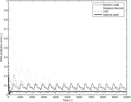
  • Results for both algorithms are shown in terms of J2 in figure 9 together with the corresponding results from the optimal static predictor and the random walk predictor.

5. WAVEFRONT RECONSTRUCTION

  • The last, but probably most important component of the controller is the wavefront reconstructor that reconstructs the wavefront phase from the gradients measured by a SHWFS.
  • Note here that the matrix GT G is singular due to the two unobservable modes of the SHWFS,5 which means that a pseudo-inverse21 must be employed to solve the system directly.
  • Thus, two options can now be considered: do the reconstruction by a dedicated external processor or find a reconstruction procedure that does fit into the framework.
  • This means that one iteration of SOR can be performed with O(nw) sequential steps.
  • This is then also the case for the required processing speed of the DPU’s and the inter-DPU communication bandwidth.

Did you find this useful? Give us your feedback

Figures (10)

Content maybe subject to copyright    Report

Distributed control in adaptive optics
Deformable mirror and turbulence modeling
Rogier Ellenbroek
a
, Michel Verhaegen
a
, Niek Doelman
b
, Roger Hamelinck
c
, Nick Rosielle
c
and
Maarten Steinbuch
c
a
Delft University of Technology, Mekelweg 2, 2628 CD Delft, The Netherlands;
b
TNO Science and Industry, Stieltjesweg 1, 2628 CK Delft, The Netherlands;
c
Technische Universiteit Eindhoven, Den Dolech 2, 5600 MB, The Netherlands
ABSTRACT
Future large optical telescopes require adaptive optics (AO) systems whose deformable mirrors (DM) have ever
more degrees of freedom. This paper describes advances that are made in a project aimed to design a new AO
system that is extendible to meet tomorrow’s specifications. Advances on the mechanical design are reported in
a companion paper [6272-75], whereas this paper discusses the controller design aspects.
The numerical complexity of controller designs often used for AO scales with the fourth power in the diameter
of the telescope’s primary mirror. For future large telescopes this will undoubtedly become a critical aspect.
This paper demonstrates the feasibility of solving this issue with a distributed controller design. A distributed
framework will be introduced in which each actuator has a separate processor that can communicate with a few
direct neighbors. First, the DM will be modeled and shown to be compatible with the framework. Then, adaptive
turbulence models that fit the framework will be shown to adequately capture the spatio-temporal behavior of
the atmospheric disturbance, constituting a first step towards a distributed optimal control. Finally, the wave-
front reconstruction step is fitted into the distributed framework such that the computational complexity for
each processor increases only linearly with the telescope diameter.
1. INTRODUCTION
Over the years, adaptive optics (AO) has grown from wild ideas to a proven technology that is indispensable for
any large telescope. Inspired by its success, ideas have sprouted for larger and larger telescopes to look at even
more distant and fainter stellar objects. However, the performance of a large telescope depends greatly upon the
number of degrees of freedom in the deformable mirror (DM) of the AO system. This number should grow with
the area of the primary mirror and thus quadratic in the telescope diameter.
Standard control approaches for AO consist of operations that typically scale with the number of actuators
squared, which means that the total computational complexity of the controller increases with the telescope
diameter to the fourth power. However, as the temporal controller bandwidth should be related to the number
of actuators per area, which is more or less constant, this may not be decreased for larger telescopes. More
efficient implementations will therefore be required for the control algorithms themselves. Many results towards
realizing this are already available,
1, 2
but few methods implemented for AO fully exploit all available wavefront
information. Moreover, the computational load of a controller that does attempt this
3
also scales with the
telescope diameter to the fourth power and no efficient implementations for such a controller exists yet.
This paper reports on work that has been done in a joint project aimed at designing a new AO system that
has an extendible design, which means that the same design should be applicable when the number of actuators
is increased. Advances in the design of the DM are discussed in,
4
while this paper focusses on the controller
design, for which a fully distributed control approach will be introduced. The goal of this controller is to yield
optimal performance in terms of rms wavefront error while distributing calculations over a geometric grid of
locally connected processors that each control one actuator. Feasibility of such a design depends on the available
locality in the AO system itself, which will be investigated. Moreover, approaches for solving several arising
problems will be discussed.
Further author information: Send correspondence to R. Ellenbroek. E-mail: r.m.l.ellenbroek@dcsc.tudelft.nl, Tele-
phone: +31 (0)152783371
Advances in Adaptive Optics II, edited by Brent L. Ellerbroek, Domenico Bonaccini Calia,
Proc. of SPIE Vol. 6272, 62723K, (2006) · 0277-786X/06/$15 · doi: 10.1117/12.671688
Proc. of SPIE Vol. 6272 62723K-1
Downloaded from SPIE Digital Library on 21 May 2010 to 131.180.130.114. Terms of Use: http://spiedl.org/terms

Controller design for AO systems is not a trivial task. Classically, controller design consists of an integrator
structure
5
in which the measured gradient vector
S
k
from the wavefront sensor (WFS) at time instant k is first
reconstructed to a wavefront error vector e
k
. This reconstruction step can be written as a matrix product of the
reconstruction matrix G
#
, which is the pseudo-inverse of the geometry matrix and the slope vector
S
k
(section
5):
e
k
= G
#
S
k
. (1)
The resulting wavefront is then mapped back into an update vector
d
k
for the actuator commands u
k
as
d
k
= B
1
e
k
, (2)
where B is the mirror influence function matrix,
5
which contains the influence of a unit actuator command for
each actuator to wavefront phase at all actuator locations in its columns. The update
d
k
is subsequently used
to update the command vector u
k
as
u
k+1
=(1 β)u
k
+ α
d
k
(3)
where α is the integrator gain and β the integrator leak factor that are tuned such that the closed loop is stable
and the mean square wavefront error e
T
k
e
k
is minimized.
This strategy only performs well if neither the DM, nor the wavefront sensor shows any detrimental dynamics
or delays. In practice this is never the case, as there is always the delay of the wavefront sensor that integrates
photons over time and the calculation time needed by a computer to calculate the command vector. By using
the classical integrator, one in fact assumes that the atmospheric disturbance can be well predicted by the last
measurement sample.
6
The faster the behavior of the atmospheric disturbance w.r.t. the sampling frequency,
the less this holds.
Therefore, many different control schemes have been devised that try to tackle these shortcomings.
6–8
Often, the
atmospheric disturbance is assumed to show a frozen flow characteristic, which makes it well predictable.
8
On the
other hand, according to some this is only due to the low-pass filtering effect of the Shack-Hartmann wavefront
sensor
9
(SHWFS). However, prediction models have scarcely been incorporated into a controller design. Some
problems are that these models are based on strong assumptions, such as Kolmogorov statistics and Brownian
motion,
9
completely frozen flow
10
or need external measurements such as wind speed and direction.
11
On the
other hand, methods do exist that adapt their wavefront reconstruction step to measured wavefront statistics
12
in closed loop.
In a recent paper,
3
an optimal controller design is demonstrated which comprehends a turbulence model that
is based on open loop wavefront sensor data and doesn’t make any presumptions on its behavior. However,
the resulting controller matrices are fully dense and do not seem to possess structure that can be exploited for
distributed implementations. In order to overcome this, an attempt is made in this paper to fit each of the
controller’s components into a distributed control framework: the mapping of a desired DM shape into a set of
DM actuator command signals, the wavefront prediction and its reconstruction.
This distributed control framework will first be introduced in section 2, after which each of the components will
be discussed. In section 3 the DM will be modeled both statically and dynamically. In section 4 a distributed
turbulence model will be evaluated and finally in section 5 the distributed wavefront reconstruction problem will
be examined.
2. DISTRIBUTED CONTROL DESIGN FRAMEWORK
In this section, the concept of distributed control is formulated in more detail. The distributed controller
framework consists of a grid of processors called Distributed Processing Units (DPU) that each control one
actuator of the deformable mirror. These DPU’s have thus the same regular geometric grid layout as the
actuators. Here it is assumed that this is a hexagonal grid, but all of the following can easily be transformed
into a square grid layout. It is further assumed that the SHWFS measurement grid has the same structure as
the actuator grid and is aligned with this such that each spot lies in the geometric center of four neighboring
actuators (figure 1). This corresponds to the often used Fried geometry, with actuators on the phase point
locations. Wavefront slope information extracted from each spot is known only to the four surrounding DPU’s.
Proc. of SPIE Vol. 6272 62723K-2
Downloaded from SPIE Digital Library on 21 May 2010 to 131.180.130.114. Terms of Use: http://spiedl.org/terms

(3,2)
(2,1)
(1,2)
(3,1)
(2,2)
(2,3)
(1,3)
(1,1)
(3,3)
Figure 1. The distributed framework in a hexagonal lay-
out. DPU’s are represented by rectangles containing their
geometric coordinates. They can communicate via the solid
communication lines. The grey filled circles represent the
SHWFS measurement spots.
Figure 2. General design of the deformable mirror as de-
scribed in detail in.
4
The layered design consists of a de-
formable reflective surface, connection rods to the actuators
in the actuator plate and a stiff support structure from top
to bottom respectively.
Further, the controllers have the ability to communicate with four directly surrounding neighbors. The controller
located at coordinate (i, j) can communicate to (i 1,j 1),(i 1,j + 1),(i +1,j + 1) and (i +1,j 1). If
communication is required to other, more remote DPU’s, this requires multiple sequential steps that take time
and should be avoided as much as possible.
Locality. In this paper, the system property locality is used. Let this be defined as the relative accuracy
with which it is possible to describe the behavior of the system using only local information when compared to
using all information. Local information is information known to either a single DPU or to its direct neighbors.
Although the number of direct neighbors may be chosen arbitrarily by defining a maximum geometric inter-
actuator distance, it does not scale with the system dimensions. This links locality directly to scalability:ifa
system has a high locality then its behavior can be well described using a limited set of local information that
does not grow with the dimensions of the system.
Calculations and notation. In the sequel, when computations are said to fit within the distributed framework,
this means that they can be performed either directly by a local DPU or by first receiving information from
neighbors to which it has a direct communication link, i.e. its connections. Let a vector of which each element
is only known to a single corresponding DPU be denoted by ˜v. For often used matrix-vector products ˜w = M ˜v,
this implies that M must have a specific sparse structure: the i
th
row of M may only contain non-zero elements
at positions that correspond to the connections of DPU i.
However, when a computation requires not only information from the DPU’s connections, but also from a limited
set (i.e. whose size is independent of the system dimensions) of other neighboring DPU’s, this can also be fit
into the distributed framework. This just yields a fixed number of sequential communication steps.
3. MIRROR MODELING
The DM for which the distributed controller is designed,
4
is of the continuous face-sheet type. This section
comprehends the DM modeling that is relevant for controller design and will be used to answer the following
questions:
1. What is the locality of the mirror’s influence functions?
2. Will the dynamics of the DM be relevant for the controller design?
3. How much damping will be required in the actuators?
The general mirror design is depicted in figure 2 and consists of a thin deformable reflective face-sheet that is
supported by electromagnetic push-pull actuators. They are connected to the reflective face-sheet with thin rods,
Proc. of SPIE Vol. 6272 62723K-3
Downloaded from SPIE Digital Library on 21 May 2010 to 131.180.130.114. Terms of Use: http://spiedl.org/terms

0
5
10
15
x 10
−4
0
2
4
6
8
x 10
−4
0
1
2
3
4
5
x 10
−4
0
1
2
3
x 10
−4
0 1 2 3 4 5 6 7 8 9 10
10
−9
10
−8
10
−7
10
−6
10
−5
10
−4
10
−3
10
−2
10
−1
10
0
Distance [unit actuator spacings]
Normalized magnitude [−]
k
a
= 100 [N/m]
× k
a
= 500 [N/m]
+ k
a
= 1000 [N/m]
o k
a
= 2000 [N/m]
Figure 3. Influence functions in [m/N] for the central ac-
tuator in a mirror with a hexagonal actuator grid with 61
actuators with a stiffness of 100, 500, 1000 and 2000 [N/m]
from left to right and top to bottom respectively.
Figure 4. Lines: normalized influence function maximum
magnitude versus actuator spacing unit distances. Marks:
normalized magnitude of the corresponding inverse matrix.
thus fixing only the out of plane deformation and are attached to a stiff support structure that gives the mirror
a flat reference.
The following subsections comprehend the modeling and identification of a single actuator which is subsequently
used to create both static as well as dynamic models of the complete DM. The implications of the result for a
distributed controller design will be evaluated.
3.1. Actuator modeling and identification
The actuators consist of a closed magnetic circuit in which a permanent magnet provides a static magnetic
force on a ferromagnetic core which is suspended in a membrane. By applying a current through the coil
which is situated around the magnet, this force is influenced, providing movement of the ferromagnetic core.
This movement is transferred via a rod imposing the out-of plane displacements in the reflective deformable
membrane. In the actuator design a match is made between the negative stiffness of the magnet and the positive
stiffness of the membrane suspension. Although this is non-linear w.r.t. the membrane deflection, the eventual
operating range of the actuator is small enough to justify a linear model.
The actuator can be straightforwardly modeled as a linear mass-spring-damper system. The moving mass consists
of the actuator membrane and the rod, the spring is the net mechanical actuator stiffness and the damping can
be either due to air flow inside the housing or due to electronics (e.g. back-EMF of the coil being dissipated in a
resistor). The actuator has been built and a set of input-output data was obtained by measuring the membrane
deflection while feeding the coil a white noise current signal. From this data, the following mass m
a
, stiffness k
a
and damping b
a
values were estimated via frequency domain identification:
m
a
=9.9 · 10
3
[g],b
a
=1.4 · 10
3
[Ns/m],k
a
= 330[N/m]. (4)
3.2. Modeling the deformable face-sheet
Although the face-sheet has only a slight thickness, it still has a considerable out-of-plane stiffness when and
should be modeled as a thin plate.
13
The thin rods connecting the actuators to the plate will be assumed to
exert point-forces, which allows the use of the analytical solution to the biharmonic equation.
14
For a circular
plate of radius r
plate
with clamped edge conditions (no deflection or out-of-plane rotation at the edge) the plate
deformation can be calculated as:
h(F, z, ζ)=
F
16πR
(1 r
2
)(1 ρ
2
)+
r
2
+ ρ
2
2 cos(φ ψ)
ln
r
2
+ ρ
2
2 cos(φ ψ)
1+r
2
ρ
2
2 cos(φ ψ)
, (5)
Proc. of SPIE Vol. 6272 62723K-4
Downloaded from SPIE Digital Library on 21 May 2010 to 131.180.130.114. Terms of Use: http://spiedl.org/terms

where h(F, z,ζ) expresses the plate deflection at position z due to a perpendicular point-force F at position ζ.
Positions z and ζ are defined in the complex plane as z = re
and ζ = ρe
respectively, where r and ρ are
normalized w.r.t r
plate
. Further, R is the flexural rigidity of the plate, which is defined as:
R =
Et
3
12(1 µ
2
)r
2
plate
, (6)
where E is the Young’s modulus of the plate material, µ its Poisson ratio and t its thickness. The equation is
linear in the force F and because of the small deflections (O(µm)) it is sufficiently accurate to use superposition
of deflections due to individual forces in case of multiple simultaneous point-forces.
Let the deflection of the plate be given as a vector
h, defined on a limited set of discrete points D. This set
comprehends all points at which a force acts on the plate. These forces are both the supporting actuator forces
as well as lumped inertia forces of the thin plate itself, that are spread over a fine grid. The forces are contained
in the vector
F , which can be related to the deflection
h via a stiffness matrix K with elements K
i,j
:
K
F =
h, K
i,j
=
∂h(F, z
i
j
)
∂F
, (7)
where both i and j enumerate all points in D. A force equilibrium is now sought that satisfies
(M
p
+ M
a
)
¨
h +(
B
p
+ B
a
)
˙
h +
F +
C
a
h =
F
a
(8)
where
C
a
, M
p
, M
a
, B
p
and B
a
are all diagonal matrices containing the actuator stiffness, plate inertia, actuator
inertia, plate air-damping and actuator damping terms respectively.
F
a
is a vector containing the actuator forces.
Using (7), a standard dynamical system form is obtained with mass, damping and stiffness matrices
M
a
+ M
p
,
B
a
+ B
p
and K
1
+ C
a
respectively. Note that if a certain grid point does not have an external force, mass,
stiffness or damping, the entry in the corresponding matrix or vector is zero.
The static case: influence functions. For the static case, all time-derivative terms in (8) are zero and
the deflection
h can be directly expressed in terms of the forces
F
a
, from which the mirror influence matrix B
containing the DM influence functions in its columns can be derived:
B =(K
1
+ C
a
)
1
. (9)
The influence function of a mirror’s central actuator has been plotted for four values of k
a
in figure 3. It can
be observed that this stiffness significantly affects the width of the influence function. This can be seen even
more clearly from figure 4, in which the lines represent the normalized maximum absolute DM deflection on
a circle with certain radius around the poked actuator. For k
a
= 1000 [N/m], that will be aimed for in the
mechanical design, the deflection of the 4
th
neighboring actuator already remains below one thousandth of the
central deflection. For an actuator range in the order of [µm], this is a deformation in the order of [nm], which
can be disregarded without affecting the optical quality.
However, calculation of the actuator commands corresponding to a desired DM shape involves the inverse of the
influence matrix B. The question relevant for distributed controller design is thus whether the locality is retained
in the inverse mapping B
1
˜
φ. This can be observed to be the case from the markers in figure 4, which show
the normalized magnitude of the elements of the i
th
row of B
1
that correspond to phase points at a certain
distance in unit actuator spacings from actuator i. This magnitude decreases also very fast with the distance
and is only slightly influenced by k
a
. Moreover, the same decrease over the distance holds for larger grids, which
means that the number of neighbors needed to calculate the actuator commands stays constant for increasing
system dimensions, confirming that also the inverse mapping has a high locality.
The dynamic case: eigenmodes and damping. A system property that is also very important for controller
design is the location of its eigenfrequencies. As for any system, the DM will be much easier to control below
its first eigenfrequency, which is even more true for this system because many eigenfrequencies will be clustered
together in a small range. The eigenfrequencies can be straightforwardly calculated using the dynamical model
and are significantly affected by k
a
, as shown for the lowest eigenfrequency by the thin line in figure 5. For
Proc. of SPIE Vol. 6272 62723K-5
Downloaded from SPIE Digital Library on 21 May 2010 to 131.180.130.114. Terms of Use: http://spiedl.org/terms

Citations
More filters
Book ChapterDOI
01 Jan 2013
TL;DR: An overview of adaptive optics (AO) systems, including a brief summary of their development history and their importance in high-resolution imaging systems, can be found in this paper, where the basic optical concepts of wavefronts and aberrations are introduced.
Abstract: This chapter presents an overview of adaptive optics (AO) systems, including a brief summary of their development history and their importance in high-resolution imaging systems. The first section of this chapter introduces the basic optical concepts of wavefronts and aberrations. The operating principle of AO systems and the primary components of these systems are then presented. Covered in the last section is a review of retinal imaging AO systems, including a brief review of the history of ophthalmic imaging systems and the requirements and challenges to their practical implementation using AO systems.

38 citations

Proceedings ArticleDOI
TL;DR: A new prototype adaptive deformable mirror for future AO-systems is presented that consists of a thin continuous membrane on which push-pull actuators impose out-of-plane displacements.
Abstract: A new prototype adaptive deformable mirror for future AO-systems is presented that consists of a thin continuous membrane on which push-pull actuators impose out-of-plane displacements. Each actuator has ±10?m stroke, nanometer resolution and only mW’s heat dissipation. The mirror’s modular design makes the mechanics, electronics and control system extendable towards large numbers of actuators. Models of the mirror are derived that are validated using influence and transfer function measurements. First results of a prototype with 427 actuators are also presented.

25 citations


Cites background from "Distributed control in adaptive opt..."

  • ...The relation can then be inverted to yield: [ Fζ M ] = [ Ωζζ Uζ U ζ 0 ]−1 [ Hζ 0 ] = [ Km Kr ] Hζ , (2)...

    [...]

  • ...Substitution of (2) for Fζ into the force equilibrium in (3) yields Fa −CaHζ −KmHζ = 0 and thus the mirror deflection Hζ at the actuator positions is related to the actuator forces Fa via the influence matrix Bζ as:...

    [...]

  • ...The results from (2) can be substituted into the plate equation in (1) together with (4), yielding Hz = BzFa where Bz = (ΩzζKm+UzKr)Bζ ....

    [...]

Journal ArticleDOI
TL;DR: An FE state-space model of a faceplate DM that incorporates damping and actuator dynamics is developed and used to estimate reduced-order DM models and the model-order selection and model validation problems are addressed.
Abstract: To develop high-performance controllers for adaptive optics (AO) systems, it is essential to first derive sufficiently accurate state-space models of deformable mirrors (DMs). However, it is often challenging to develop realistic large-scale finite element (FE) state-space models that take into account the system damping, actuator dynamics, boundary conditions, and multi-physics phenomena affecting the system dynamics. Furthermore, it is challenging to establish a modeling framework capable of the automated and quick derivation of state-space models for different actuator configurations and system geometries. On the other hand, for accurate model-based control and system monitoring, it is often necessary to estimate state-space models from the experimental data. However, this is a challenging problem since the DM dynamics is inherently infinite-dimensional and it is characterized by a large number of eigenmodes and eigenfrequencies. In this paper, we provide modeling and estimation frameworks that address these challenges. We develop an FE state-space model of a faceplate DM that incorporates damping and actuator dynamics. We investigate the frequency and time domain responses for different model parameters. The state-space modeling process is completely automated using the LiveLink for MATLAB toolbox that is incorporated into the COMSOL Multiphysics software package. The developed state-space model is used to generate the estimation data. This data, together with a subspace identification algorithm, is used to estimate reduced-order DM models. We address the model-order selection and model validation problems. The results of this paper provide essential modeling and estimation tools to broad AO and mechatronics scientific communities. The developed Python, MATLAB, and COMSOL Multiphysics codes are available online.

17 citations

23 Jan 2007
TL;DR: In this article, a data-driven optimal control strategy for adaptive optics (AO) systems is proposed, which consists of a dedicated subspace-identification algorithm to identify an atmospheric disturbance model from open-loop sensor data, followed by an optimal control design.
Abstract: Adaptive optics (AO) is a technique to actively correct the wavefront distortions introduced in a light beam as it propagates through a turbulent medium. Nowadays, it is commonly applied in ground-based telescopes to counteract the devastating effect of atmospheric turbulence. This thesis focuses on the control aspects of AO. Whereas most AO systems use a simple control law derived from physical insights, this thesis addresses the AO control problem from a control engineering perspective. The main objective is to show that the performance of the current generation of AO systems can be improved by applying advanced control strategies that account for the AO system dynamics and the spatio-temporal correlation in the wavefront. To this end a data-driven optimal control is proposed. It consists of a dedicated subspace-identification algorithm to identify an atmospheric disturbance model from open-loop wavefront sensor data, followed by an optimal control design. By an efficient implementation, this approach can be used to design a full multi-variable controller for AO systems with up to a few hundred sensors and actuators, without assuming any form of decoupling. The data-driven optimal control strategy is thoroughly tested both in simulations and on an AO laboratory setup. The experiments show, that compared to the standard approach, optimal control is able to improve the wavefront suppression performance, especially under low light level conditions and rough turbulence. The gain in performance is explained the improved ability to anticipate future distortions when accounting for the spatio-temporal correlation in the wavefront.

17 citations


Cites background from "Distributed control in adaptive opt..."

  • ...2004, 2005a,b, 2006), (Ellenbroek et al. 2006) proposed a distributed control framework for AO in which each actuator has a separate processor that can communicate with a few direct neighbors....

    [...]

Journal ArticleDOI
TL;DR: This paper attempts to adopt the benefits of ILC to improve the trajectory tracking performance of spatially interconnected systems by utilizing the ILC update law along the iteration domain repetitively to ensure a perfect reference trajectory tracking.

14 citations

References
More filters
01 Jan 2003

3,254 citations

Book
19 Apr 1996
TL;DR: The main thrust is to provide students with a solid understanding of a number of important and related advanced topics in digital signal processing such as Wiener filters, power spectrum estimation, signal modeling and adaptive filtering.
Abstract: From the Publisher: The main thrust is to provide students with a solid understanding of a number of important and related advanced topics in digital signal processing such as Wiener filters, power spectrum estimation, signal modeling and adaptive filtering. Scores of worked examples illustrate fine points, compare techniques and algorithms and facilitate comprehension of fundamental concepts. Also features an abundance of interesting and challenging problems at the end of every chapter.

2,549 citations


"Distributed control in adaptive opt..." refers background in this paper

  • ...(20) As both Rk and ṽk converge to the best estimates for the covariance matrix R and correlation vector ṽ respectively for k → ∞, the adaptive filter should converge to the static solution as long as the step size α is chosen properly....

    [...]

Journal ArticleDOI
TL;DR: In this article, a review of the algebras related to Kronecker products is presented, which have several applications in system theory including the analysis of stochastic steady state.
Abstract: The paper begins with a review of the algebras related to Kronecker products. These algebras have several applications in system theory including the analysis of stochastic steady state. The calculus of matrix valued functions of matrices is reviewed in the second part of the paper. This calculus is then used to develop an interesting new method for the identifiication of parameters of lnear time-invariant system models.

1,944 citations

Book
30 Jul 1998

911 citations


Additional excerpts

  • ...h(F, z, ζ) = F 16πR { (1 − r(2))(1 − ρ(2)) + [r2 + ρ(2) − 2rρ cos(φ − ψ)] ln r(2) + ρ(2) − 2rρ cos(φ − ψ) 1 + r2ρ2 − 2rρ cos(φ − ψ) } , (5)...

    [...]

Frequently Asked Questions (8)
Q1. what are the next steps to the DM?

Next steps will be the closing of the control loop in simulations, design of the driving electronics for the DM and experimental validation on a breadboard. 

The undamped system has a highly oscillating step response, requiring over 100 times more actuator damping than that estimated in section 3.1 to suppress. 

The actuators consist of a closed magnetic circuit in which a permanent magnet provides a static magnetic force on a ferromagnetic core which is suspended in a membrane. 

But again due to the structure of A when the points in the phase grid are suitably ordered, this forward substitution problem can be written as a series of nf ≈ nw/2 elimination steps – where nw is the number of phase points over the diagonal of the grid. 

(4)Although the face-sheet has only a slight thickness, it still has a considerable out-of-plane stiffness when and should be modeled as a thin plate. 

For the static case, all time-derivative terms in (8) are zero and the deflection h can be directly expressed in terms of the forces Fa, from which the mirror influence matrix B containing the DM influence functions in its columns can be derived:B = (K−1 + Ca)−1. (9)The influence function of a mirror’s central actuator has been plotted for four values of ka in figure 3. 

This paper reports on work that has been done in a joint project aimed at designing a new AO system that has an extendible design, which means that the same design should be applicable when the number of actuators is increased. 

Models based on Kolmogorov statistics such as16,17 work well, but apart from pure frozen flow behavior it appears difficult to model the evolution of the disturbance over time.