scispace - formally typeset
Search or ask a question
Journal ArticleDOI

Experimental Investigation Into Laser Ranging With Sub-ns Laser Pulses

01 Feb 2018-IEEE Sensors Journal (IEEE)-Vol. 18, Iss: 3, pp 1047-1053
TL;DR: In this paper, a high-precision time-of-flight laser radar system based on energetic (~ 0.6 nJ) sub-ns laser pulses produced with a semiconductor laser diode is presented.
Abstract: We present a high-precision time-of-flight laser radar system based on energetic (~ 0.6 nJ) sub-ns laser pulses produced with a semiconductor laser diode. The proposed device has a single-shot precision of <5 mm at an SNR of 10 and a maximum walk error <500 ps in the dynamic range 1:250. Sub-mm precision can be achieved in ranging by means of averaging. The proposed laser radar can be used for monitoring tiny vibrations in distant targets, for example.

Summary (2 min read)

Introduction

  • Abstract—We present a high precision time-of-flight (TOF) laser radar system based on energetic (~ 0.6 nJ) sub-ns laser pulses produced with a semiconductor laser diode.the authors.
  • Pulsed TOF laser radars typically use high energy pulses with lengths of 3 – 5 ns, allowing a single-shot precision of a few centimetres [9].
  • When sub-cm single-shot precision is aimed at, the jitter in the timing detection should be minimized.
  • It is well known that This paragraph of the first footnote will contain the date on which you submitted your paper for review.

II. DESIGN PRINCIPLES AND SUB-NS DETECTION

  • Typical pulsed TOF laser radars intended for industrial applications use a laser diode transmitter producing high power (> 10 W) pulses with a typical length of < 5 ns (FWHM).
  • The pulse length is limited to the nanosecond range due to the limitations of high-current (peak current > 10 A), high speed drivers [17, 18].
  • The bandwidth of the receiver channel was set to ~ 700 MHz, being limited by the technology used in the proposed receiver configuration.
  • The responsivity of a CMOS APD is low compared with a discrete one, but due to its speed and integration possibility, this is an interesting detector option for a laser range finder using sub-ns pulses.
  • There can be wide variations in the power of the received echo (the amplitude of the APD response) in TOF-based laser radars, and this causes the shift for the detection moment of the pulse resulting a systematic error.

III. CONSTRUCTION OF THE LASER RADAR

  • The laser radar constructed here consists of a receiver APD detector (discrete: diameter 100 µm, CMOS: 20 µm x 40 µm), paraxial optics, a laser transmitter and the receiver electronics, including the receiver channel, time-to-digital converter (TDC) and controlling FPGA board.
  • The laser radar has a transmitter using a MOSFET-based driver presented in [21].
  • The transimpedance amplifier and the comparator use a 1.8 V supply voltage, but thanks to the high voltage (HV) design, the internal level shifters giving a 2.5 to 5 V output are located in the chip and can thus be used with a time-to-digital converter (TDC) using a supply voltage of 3.3 V.
  • A photograph of the receiver channel chip is shown in Fig.
  • The FPGA board also resets the comparators after reading the TDC data, so that the laser radar device is ready for the next measurement.

IV. MEASUREMENTS

  • The measurements were carried out using a sheet of white paper with diffuse reflectance of ε ~ 1 as the reference target.
  • The input-referred detection noise was 450 nA so that the noise level at the output of the receiver was 11.5 mV when the transimpedance of the channel was 25 kΩ.
  • The walk error was measured by sweeping the amplitude of the laser pulse from SNR = 10 to SNR = 2,500 (setting the comparator threshold at SNR = 7).
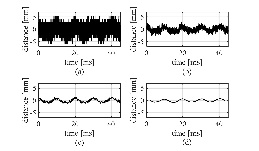
  • The precision of the system with respect to distance measurement is demonstrated in Fig. 14.
  • Single-shot measurement results were recorded at a pulsing rate of 24 kHz. Fig. 14 a) shows the measurements without averaging (single-shot) and b), c) and d) the averaged results of 10, 100 and 1,000 single-shot measurements, respectively.

V. CONCLUSIONS

  • The hardware (HW) of the TOF-based laser radar using sub-ns laser pulses presented here consists of a MOS-based laser diode transmitter generating ~ 100 ps 0.6 nJ laser pulses, receiver electronics including a full-custom 0.18 µm HVCMOS receiver channel, a full-custom 0.35 µm CMOS TDC and an FPGAbased control board.
  • The key result of this work is that it demonstrates sub-mm precision with a relatively short measuring time.
  • The good jitter properties of the present laser radar are due to the high speed of its pulse, and the short pulse width gives an additional advantage of enabling the resolution of better targets that are close to each other and under the laser beam.
  • On the other hand, the optical energy is also lower (as compared with a pulse width of 3–5 ns), limiting the maximum range.
  • This would give a good combination of high single-shot precision and sensitivity due to the improved signal-to-noise ratio.

Did you find this useful? Give us your feedback

Content maybe subject to copyright    Report

> REPLACE THIS LINE WITH YOUR PAPER IDENTIFICATION NUMBER (DOUBLE-CLICK HERE TO EDIT) <
1
AbstractWe present a high precision time-of-flight (TOF)
laser radar system based on energetic (~ 0.6 nJ) sub-ns laser
pulses produced with a semiconductor laser diode. The
proposed device has a single-shot precision of < 5 mm at an
SNR of 10 and a maximum walk error < 500 ps in the
dynamic range 1:250. Sub-mm precision can be achieved in
ranging by means of averaging. The proposed laser radar
can be used for monitoring tiny vibrations in distant targets,
for example.
Index Terms—Laser radar, laser rangefinding, optical
receivers, optical sensors.
I. INTRODUCTION
pulsed time-of-flight laser radar operates by measuring the
transit time of a short laser pulse sent to the target and
scattered back to the receiver. The distance from the target can
then be calculated based on the known velocity of light [1]. The
precision of laser radars is improving constantly, and
simplicity, cost and high measurement speed (since the target
may be moving) are important factors that have paved the way
for the use of TOF techniques in industrial applications [2–8].
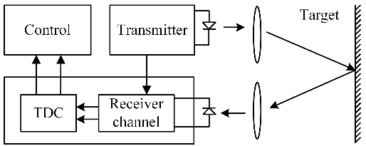
The construction of a typical pulsed TOF laser radar system is
shown in Fig. 1.
Pulsed TOF laser radars typically use high energ y pulses with
lengths of 3 – 5 ns, allowing a single-shot precision of a few
centimetres [9]. This precision can be improved by averaging
multiple single measurements, but of course at the expense of
increased measurement time. For example, if a 10 kHz pulsing
frequency is used (typical of high power avalanche-type pulsing
devices) the averaging of 100 measurements takes 10 ms. The
main factors limiting the precision are detection noise and the
timing walk (walk error) caused by variation in the amplitude
of the received echo pulse [9]. Due to the relatively wide laser
pulse, the walk error needs to be compensated for in distance
measurement applications where high accuracy is needed.
However, in measurements where small changes in distance are
to be detected on top of a long base distance, e.g. where
measurements are affected by tiny vibration, the walk error
compensation is not crucial, since the variation in the amplitude
of the received pulse is small.
When sub-cm single-shot precision is aimed at, the jitter in
the timing detection should be minimized. It is well known that
This paragraph of the first footnote will contain the date on which you
submitted your paper for review. This work was supported by the Academy of
Finland.
jitter is proportional to the ratio of the receiver noise to the slew
rate of the timing signal [10]. The rise time of the laser pulse in
typical radars using 3 – 5 ns pulses is of the order of a few ns,
but if the laser diode is driven into the gain switching mode, a
significantly shorter pulse (~ 100 ps) with a lower energy level
(< 0.1 nJ) can be produced [11, 12]. It has been shown recently,
however, that it is possible to markedly enhance the gain
switching by increasing the equivalent spot size (d/gamma) of
the laser diode. As a result, laser pulses with an energy of > 1 nJ
(10 W) and length of ~ 100 ps were produced with pulse current
drive parameters of ~ 10 A/1 ns/100 kHz [13, 14].
The goal of the present pulsed TOF study was to use this
high-speed sub-ns transmitter to achieve sub-mm precision
when measuring distances from passive targets. The interest lay
in trying to detect small distance variations (e.g. vibrations in a
machine) from a distance away. On the other hand, the short
laser pulse width (= short probe length) enables better resolve
double echoes which are produced when part of the laser beam
hits a second, more distant target in addition to the primary one.
An Avalanche Photo detector (APD) is typically used as the
detector component in laser range-finder applications, due to its
internal gain [15]. A silicon-based CMOS APD device would
offer low cost, fast response and the possibility of integrating
the detector with the receiver and other electronics on the same
chip, but its responsivity is markedly lower than that of
specialized commercial photo-detectors [16]. The
measurements in this work, were made mainly using a discrete
APD, but a CMOS-based APD chip was also tested for asses its
usability in pulsed TOF ranging.
The paper is organized as follows: Section II describes the
design principles and background theory, after which the
construction of a laser radar device is explained in section III.
Section IV presents the measurement results and an evaluation
of the performance of the range finder. Conclusions are drawn
in section V.
II. DESIGN PRINCIPLES AND SUB-NS DETECTION
Typical pulsed TOF laser radars intended for industrial
applications use a laser diode transmitter producing high power
(> 10 W) pulses with a typical length of < 5 ns (FWHM). The
pulse length is limited to the nanosecond range due to the
limitations of high-current (peak current > 10 A), high speed
drivers [17, 18]. However, a number of special gain-switched
laser constructions have been suggested which can produce
energetic sub-ns range pulses [19, 20]. In particular, ‘enhanced
The authors are with the Circuits and Systems research group, University of
Oulu, 90014 University of Oulu, Finland (e-mail: mikko.hintikka@oulu.fi;
juha.kostamovaara@oulu.fi ).
M. Hintikka and J. Kostamovaara, Senior Member, IEEE
Experimental investigation into laser ranging
with sub-ns laser pulses
A

> REPLACE THIS LINE WITH YOUR PAPER IDENTIFICATION NUMBER (DOUBLE-CLICK HERE TO EDIT) <
2
gain switching’-based constructions are capable of producing
laser pulses with an energy level of ~ nJ and a pulse width of
~100 ps [13, 14, 20].
The laser diode transmitter used here had a MOSFET current
driver and a quantum well GaAs/GaAlAs laser diode working
in the enhanced gain switching regime [21]. This produces
optical pulses with a peak power of 6 W and a pulse width of
~ 100 ps. A discrete APD is used as the photo-detector of the
laser radar because of the high sensitivity attributable to its
internal gain. The sensitivity is reduced with fast pulsing due to
the limited bandwidth, as shown in [16], but it was still
measured to be about 10 A/W. When detecting sub-ns pulses,
the bandwidth of the receiver should be matched accordingly.
For a pulse width of 100 ps (FWHM), for example, a bandwidth
of ~ 3.5 GHz (BW = 0.35/tr) would be needed. The limited
speed of the APD (width of the impulse response ~ 300 ps)
nevertheless restricts the bandwidth requirement of the receiver
to the GHz range. In this work, the bandwidth of the receiver
channel was set to ~ 700 MHz, being limited by the technology
used in the proposed receiver configuration. Note, however,
that even though the bandwidth is lower than optimum, the
effect on the jitter is only minor, since a higher bandwidth
would increase the noise as well. The responsivity of a CMOS
APD is low compared with a discrete one, but due to its speed
and integration possibility, this is an interesting detector option
for a laser range finder using sub-ns pulses. For this reason,
even though a commercial discrete APD (AD100-8 SMD from
First Sensor) was used in the majority of the measurements, the
usability of a CMOS APD was also tested by replacing the
discrete APD with a standalone CMOS APD chip (realized in
0.35 µm CMOS technology) for some measurements.
The radar equation, giving an estimate for the received
power, can be written for a non-cooperative (Lambertian) target
as
(
)
=
, (1)
where
(
)
is the power of the receiver aperture as a function
of the distance Z,
is the optical power of the transmitter,
is
the area of the receiver optics, is the reflectance of the diffuse
target and is the efficiency of the optics [22]. The radar
equation enables one to optimize the performance of the system
and to seek the optimum balance in the design parameters. This
will enable estimation of the signal current used in detection, so
that the signal-to-noise ratio and valid distance measurement
range can be calculated. For example, the responsivity of the
APD and the input-referred noise of the TIA obtained here for
the receiver are 10 A/W and 450 nA (rms), respectively,
meaning that primary signal current of about 450 nA in the
detector will give an SNR of 10 for the receiver (where SNR is
defined as the ratio of the peak signal current to the input-
referred total noise current of the preamplifier). From (1) we
can calculate that for a typical 6 W pulse from the above-
mentioned laser diode transmitter, a receiver aperture of 20 mm,
optics efficiency of 0.7 and a target having ε = 0.1, the
maximum achievable distance measurement range is ~ 10 m.
As already mentioned above, jitter is proportional to the
ratio of the receiver noise to the slew rate of the timing
signal. [10]:
( )
SNR
t
tv
r
noise
jitter
σ
σ
and
.
2
c
SNR
t
r
R
×
σ
(2)
Thus, as the rise time of the pulse decreases, the jitter will
decrease as well if the SNR remains the same. The jitter directly
affects the single-shot range precision of the laser radar (
R
σ
).
There can be wide variations in the power of the received
echo (the amplitude of the APD response) in TOF-based laser
radars, and this causes the shift for the detection moment of the
pulse resulting a systematic error. This is usually called timing
walk [9]. Several techniques for compensating for the walk
error have been presented, see [23–27] and the references
therein, but it is quite obvious that the inherent walk error will
be lower with shorter laser pulses, as illustrated in Fig. 2.
One challenge in TOF-based laser ranging is the change in
the shape of the echo according to the orientation of the target.
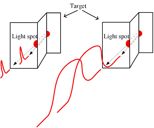
In extreme cases even multiple echoes can be detected, as is
shown in Fig. 3, where the laser spot is split in half at a sharp
edge on the target. In the case illustrated in Fig. 3 the pulse
shape grows wide depending on the depth of the step in the
target. When the step is deep enough, two different pulses
reflect from the target (each half of the spot). Thus, it depends
strongly on the width of the pulse as to how short the distance
differences are that can be resolved with the radar. The situation
shown in Fig. 3 is one in which the edge can be identified with
a sub-ns pulse, and it also illustrates the situation with a wider
pulse when identification is not possible.
III. CONSTRUCTION OF THE LASER RADAR
The laser radar constructed here consists of a receiver APD
detector (discrete: diameter 100 µm, CMOS: 20 µm x 40 µm),
paraxial optics, a laser transmitter and the receiver electronics,
including the receiver channel, time-to-digital converter (TDC)
and controlling FPGA board. A block diagram of the system
device is presented in Fig. 4.
The laser radar has a transmitter using a MOSFET-based
driver presented in [21]. This is a compact pulser emitting ~
0.6 nJ/100 ps pulses up to a pulsing frequency of over 100 kHz.
The high pulsing frequency is achieved using a MOSFET
transistor in the pulsing device instead of an avalanche
transistor with a high on-voltage. The laser diode is based on a
quantum well structure with a cavity length of 1.5 mm and an
emitting stripe width of 30 µm [20]. The schematics of the
driver are presented in Fig. 5 and a photograph of the laser
transmitter is shown in Fig. 6. The light emitted by the laser
diode was focused on the fibre carrying light to the transmitter
optics.
The receiver uses paraxial optics in which the focal lengths
of the transmitter and receiver optics are 30 mm and 20 mm,
respectively. The receiver aperture is 20 mm. The diameter of
the optical fibre used in focusing the transmitter was 50 µm,
which leads to a spot size of ~ 3 mm at a distance of 2 m. The
optics used here are shown in Fig. 7.
The receiver channel circuit was fabricated in a 0.18 µm
HVCMOS technology and included a transimpedance pre-
amplifier, a post-amplifier and a timing comparator which

> REPLACE THIS LINE WITH YOUR PAPER IDENTIFICATION NUMBER (DOUBLE-CLICK HERE TO EDIT) <
3
discriminates the timing signals from the leading and the
trailing edges, giving two stop pulses (Stop 1 for the leading
edge of the pulse and Stop 2 for the trailing edge) [28]. Both
edges are discriminated, which in principle also allows walk
error compensation. The bandwidth of the receiver is ~ 700
MHz and the equivalent transimpedance ~ 25 kΩ. The input
referred noise current is approximately 450 nA with a discrete
APD at the input [28]. The transimpedance amplifier and the
comparator use a 1.8 V supply voltage, but thanks to the high
voltage (HV) design, the internal level shifters giving a 2.5 to
5 V output are located in the chip and can thus be used with a
time-to-digital converter (TDC) using a supply voltage of
3.3 V. A photograph of the receiver channel chip is shown in
Fig. 8.
The time interval measurements circuit, as presented in detail
in [29], is a multichannel TDC implemented in a 0.35 µm
technology and giving a timing resolution < 10 ps. The supply
voltage of the TDC is 3.3 V and a block diagram is shown in
Fig. 9. The data obtained from the TDC (18 bytes per
measurement) are transferred to an FPGA interface by 8 parallel
lines. The FPGA board also resets the comparators after reading
the TDC data, so that the laser radar device is ready for the next
measurement. The FPGA board is controlled by the computer’s
test software.
IV. MEASUREMENTS
The measurements were carried out using a sheet of white
paper with diffuse reflectance of ε ~ 1 as the reference target.
The shape of the laser pulse as measured with a high-speed
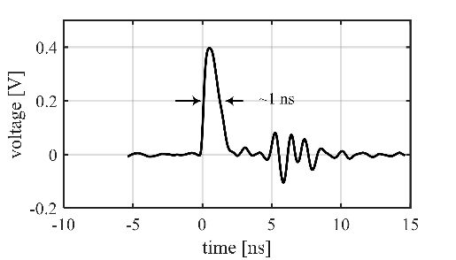
optical probe (~ 25 GHz) is shown in Fig. 10, and the response
of the receiver channel is depicted in Fig. 11. The pulse in Fig.
11 was probed from the output buffer of the receiver when
measuring a distance of 6 m. The input-referred detection noise
was 450 nA so that the noise level at the output of the receiver
was 11.5 mV when the transimpedance of the channel was
25 kΩ. The pulse of amplitude 400 mV in Fig. 11 corresponds
to an SNR of 36. The measurement is the average of 1,024
measurements, so that the noise level is attenuated. There is,
however, a periodic crosstalk bounce after the pulse which
originates from the comparator reset and does not affect the
results.
The single-shot jitter of the rising edge of the detected pulse
was measured by sweeping the amplitude of the laser pulse with
a variable neutral density filter. The jitter recorded with three
detection thresholds can be seen in Fig. 12. The threshold levels
are shown as SNR (blue: 80 mV, SRN = 7, red: 126 mV, SNR
= 11 and green: 195 mV SNR = 17). The results show an
improvement in the jitter as a function of signal amplitude (and
thus SNR), and a jitter saturation towards the bottom value
restricted by the jitter of the TDC (10 ps). The y axis on the
right shows the corresponding range jitter. Note also that the
jitter at a low signal SNR is somewhat higher for a higher
threshold (e.g. V
th
is equivalent to SNR = 17), than for lower
thresholds, on account of the decreasing signal slew rate near
the peak of the signal pulse.
The walk error was measured by sweeping the amplitude of
the laser pulse from SNR = 10 to SNR = 2,500 (setting the
comparator threshold at SNR = 7). The high SNR of 2,500
corresponds to a signal current of ~ 1 mA, which is well beyond
the linear range of the preamplifier. Note, however, that this
does not destroy the leading edge timing discrimination. Also,
external cross-coupled Schottky diodes are used to limit the
input current to the preamplifier and to speed up its recovery
from the transient. The measured walk error can be seen in Fig.
13. It is measured by sweeping the echo amplitude trough the
dynamic range of 1:250 and the Fig. 13 shows the shift of the
timing moment as a function of echo amplitude. Timing walk is
a notable source of error in TOF-based laser ranging when
measuring distances within a wide dynamic range of echo
pulses, and with the transceiver presented here it is ~ 500 ps
(7.5 cm in distance) with a linear dynamic range of the received
echo amplitudes of 1:250. This error is markedly lower than that
typically achieved in a pulsed TOF laser radar using a
conventional ns-scale pulse width, e.g. ~ 2.5 ns walk error with
a ~ 3 ns laser pulse [1, 4] or ~ 1.7 ns with an ns pulse [23].
Although the walk error is usually compensated for, it is of less
importance in this particular case, where the vibration of the
surface is mainly targeted and the echo amplitude is high and
relatively constant.
The precision of the system with respect to distance
measurement is demonstrated in Fig. 14. The target, with a step-
like profile (2 mm in height), was moved vertically (total
movement 2.5 cm) with regard to the optical axis of the laser
radar while the radar was continuously measuring the distance.
The diameter of the laser spot at a distance of 2 m was around
3 mm. Single-shot measurement results were recorded at a
pulsing rate of 24 kHz. Fig. 14 a) shows the measurements
without averaging (single-shot) and b), c) and d) the averaged
results of 10, 100 and 1,000 single-shot measurements,
respectively. It can be seen that sub-mm precision can easily be
achieved for a high signal level (SNR ~ 2,000) by means of
averaging. Averaging increases the measurement time and, as
24 kHz was used as the pulsing frequency, 100 measurements
correspond to ~ 4 ms in measurement time. On the other hand,
the transmitter enables one to use a pulsing rate of up to 100
kHz, which corresponds to a measurement time of 1 ms. In
conclusion, sub-mm precision can be achieved for relatively
rapidly vibrating surfaces. The vibrating surface was simulated
by recording the distance of an eccentric round target rolled by
an electric motor at a base distance of 2 m. The vibration
frequency and amplitude were 10 Hz and ~ 1.5 mm,
respectively. The results for single-shot measurement and for
the averaging of 10, 100, and 1,000 successive results are
shown in Fig. 15 a), b), c) and d).
The pulse probed from the output buffer of the receiver when
measuring the distance to a white paper target 1 m away when
the discrete APD detector was replaced with the standalone
CMOS APD is to be seen in Fig. 16. The detector details are
presented in [16, 30]. The reverse bias voltage was set at 18.9 V
(close to the breakdown point) in order to maximize the
response (but without any notable rise in noise level). The
measured pulse response shown in Fig. 16 demonstrates a peak
amplitude of ~ 200 mV, and a responsivity of ~ 0.3 A/W
(18.9 V bias) for the CMOS APD can be calculated from (1).
That very much lower than with the discrete APD (~ 10 A/W),
of course, but it does allow the echo pulse to be detected. In
reality, as the CMOS APD could be constructed as an on-chip

> REPLACE THIS LINE WITH YOUR PAPER IDENTIFICATION NUMBER (DOUBLE-CLICK HERE TO EDIT) <
4
device, the noise of the receiver channel would also be reduced
due to the lower input capacitance.
The light spot (of finite size) in a TOF-based laser radar may
be split when hitting the edge of the target, and thus two echo
pulses could be received (see Fig. 3). When using typical pulse
widths of 3–5 ns, the minimum resolvable distance that can be
observed is matter of several metres, but it was obviously
shorter with the sub-ns pulse and laser radar used here. The
situation for two observed echo pulses is illustrated in Fig. 17.
The distances of the two objects in the case shown in the figure
were 4.5 m and 5 m (a step of 0.5 m) and the result indicates
that the objects can be resolved. The minimum resolvable
distance is reached when the echo pulses exceed the zero level
(or the comparator threshold) between the two pulses, which
would be around 0.4 m with this setup.
V. CONCLUSIONS
The hardware (HW) of the TOF-based laser radar using sub-ns
laser pulses presented here consists of a MOS-based laser diode
transmitter generating ~ 100 ps 0.6 nJ laser pulses, receiver
electronics including a full-custom 0.18 µm HVCMOS receiver
channel, a full-custom 0.35 µm CMOS TDC and an FPGA-
based control board.
The walk error of the radar is ~ 500 ps within the dynamic
range of 1:250, and the jitter of the leading edge of the detected
pulse is limited by the TDC to ~ 10 ps at a high signal-to-noise
ratio. The key result of this work is that it demonstrates sub-mm
precision with a relatively short measuring time. For example,
it was shown that perpendicular vibration with an amplitude of
1.5 mm at a frequency of 10 Hz can be reliably observed. The
measurement speed of the current realization is limited by the
pulsing rate of 24 kHz, but this is not a fundamental limit and
can be increased above 100 kHz even with a 10 W peak pulse
power level [20, 21].
The CMOS APD tested as a detector component for the
receiver can be used successfully in a pulsed time-of-flight laser
radar when measuring short distances or using good reflectors
as targets. This is an interesting option for a detector, since it
can be integrated multiply on the same die as the receiver and
the rest of the electronics.
The good jitter properties of the present laser radar are due to
the high speed of its pulse, and the short pulse width gives an
additional advantage of enabling the resolution of better targets
that are close to each other and under the laser beam. On the
other hand, the optical energy is also lower (as compared with
a pulse width of 3–5 ns), limiting the maximum range. An
interesting compromise would then be to use a high equivalent
spot size to increase the front edge speed of the laser pulse and
drive the laser diode to a quasi-steady mode with a resulting
optical pulse width of ~ 1 ns, for example. This would give a
good combination of high single-shot precision and sensitivity
due to the improved signal-to-noise ratio.
For future improvements an increase in receiver bandwidth
would improve the walk and jitter properties, but it would also
need a TDC with better single-shot precision. Integrating the
CMOS APD and the receiver electronics on the same chip
would reduce the jitter due to the faster detector and lower input
capacitance (wider achievable bandwidth), but only at the cost
of reduced sensitivity.
ACKNOWLEDGMENTS
The authors acknowledge financial support from the
Academy of Finland (Centre of Excellence in Laser Scanning
Research, contract no. 272196, and contracts nos. 255359,
263705 and 251571) and the Infotech Oulu Graduate School.
Fig. 1. Typical block diagram of a pulsed TOF based laser range finder.
Fig. 2. Timing walk error in leading edge of the pulse.
Fig. 3. Double echo identification when the light spot is split at the target.

> REPLACE THIS LINE WITH YOUR PAPER IDENTIFICATION NUMBER (DOUBLE-CLICK HERE TO EDIT) <
5
Fig. 4. Block diagram of the laser radar proposed here.
Fig. 5. Schematic of the laser transmitter.
Fig. 6. Laser transmitter.
Fig. 7. Paraxial optics.
Fig. 8. Photograph of the receiver.
Fig. 9. Block diagram of the TDC.
Fig. 10. Laser pulse shape probed with a high speed optical probe (New port
1434-50).

Citations
More filters
Journal ArticleDOI
TL;DR: A Time-of-Flight laser radar receiver based on pulse-shaping at the input to the receiver channel, in which the first zero-crossing point of the converted pulse is marked as the timing moment to achieve high accuracy and high precision within a wide dynamic range.
Abstract: This paper presents a Time-of-Flight laser radar receiver based on pulse-shaping at the input to the receiver channel, in which the first zero-crossing point of the converted pulse is marked as the timing moment. In this technique, an LC resonator is combined with a nonlinear feedback TIA to achieve high accuracy and high precision within a wide dynamic range. The key advantage is that the receiver does not require any post compensation or gain control techniques so that the total complexity of the TOF radar is reduced considerably. Measurements made in a $0.35~\mu m$ standard CMOS process show a bandwidth of $230MHz$ and an input-referred noise of $70nA$ RMS. The receiver chip consumes $155mW$ power from a $3.3V$ supply. The single-shot precision and accuracy of the receiver within a dynamic range of 1:50,000 are $ \sim 15mm(SNR=12)$ and $\sim \pm 15mm$ respectively. A wider dynamic range can be achieved with a larger accuracy tolerance. The functionality of the proposed receiver channel is also verified over an input pulse variation and temperature range of $0~^{\mathrm {o}}\text{C}$ to $50~^{\mathrm {o}}\text{C}$ .

22 citations


Cites background from "Experimental Investigation Into Las..."

  • ...The timing jitter, which randomly affects timing detection, is proportional to the rise time of the arriving pulse [17] so that shorter pulses give better precision but it calls for a receiver with a wider bandwidth [18]....

    [...]

Journal ArticleDOI
TL;DR: In this paper, a linear-array receiver analog front-end (AFE) circuit, which mainly consists of 16 transimpedance amplifiers (TIAs), is presented for pulsed time-of-flight (TOF) rotating scanner light detection and ranging (LiDAR) application.
Abstract: A linear-array receiver analog front-end (AFE) circuit, which mainly consists of 16 transimpedance amplifiers (TIAs), is presented for pulsed time-of-flight (TOF) rotating scanner light detection and ranging (LiDAR) application. In particular, a single-channel TIA with a novel cascaded combination consists of a transimpedance preamplifier biased by a power supply of 1.8 V, a post amplifier (PA), and an output buffer (OB) with a 3.3-V power supply, aiming to lower the parasitic capacitance of the input stage and widen the output swing range, respectively. Meanwhile, the input-referred noise current is investigated to evaluate the detecting capability for the weak pulse current, and the crosstalk reduction schemes in circuit design and layout design are presented for the proposed AFE circuit. The proposed AFE circuit, which achieves a high gain of 100 dB ${\Omega }$ , a low gain of 60 dB ${\Omega }$ , a simulated transimpedance gain bandwidth of approximately 450 MHz, an equivalent input-referred noise current of 2.59 pA/Hz0.5, a signal-to-crosstalk ratio of 40.1 dB between adjacent channels, and a minimum detectable signal of $2.5~{\mu }\text{A}$ at SNR = 5, was fabricated in a 0.18- ${\mu }\text{m}$ standard CMOS technology. The total area of AFE circuit, which includes the circuit core, bandgap and bias circuits, and I/O PAD, is approximately equal to ${4.80}\times {0.85}$ mm2.

20 citations


Cites background from "Experimental Investigation Into Las..."

  • ...Recently, the pulsed width of sub-ns is typically exploited in the transmitter [18]....

    [...]

Journal ArticleDOI
TL;DR: In this paper, an online echo waveform fitting-based method is proposed for the real-time in situ laser ranging, and the results show that a single measurement of the distance can be done within $8.7~\mu \text{s}$ , which is fast enough for online ranging.
Abstract: In this paper, an online echo waveform fitting-based method is proposed for the real-time in situ laser ranging. In the method, an embedded FPGA is employed to realize the fast single-pulse fitting, and the parameters of the echo waveform of an object under detection are, thus, extracted in an online manner. The parameters of the echo waveform are utilized to estimate the time interval between the emitted pulse and the echo. The distance of the object is then calculated from the time interval. The simulations were first done to analyze and obtain the computational resource consumption and the time cost of a single measurement. Then, an FPGA- and ADC-based ranging system was designed, and an experiment was carried out to verify the proposed method. The results show that a single measurement of the distance can be done within $8.7~\mu \text{s}$ , which is fast enough for online ranging. At a distance of 70 m with an SNR of 18.4 dB, the mean range error and the range standard deviation are 4.9 and 10.7 cm, respectively. In addition, the proposed method was also compared with the TDC-based in situ method and the Gauss–Newton algorithm-based off-line method.

14 citations


Cites methods from "Experimental Investigation Into Las..."

  • ...L IGHT detection and ranging (LiDAR), using the timeof-flight method, is the most effective laser ranging technology for measuring the distance from the observer to the object [1]–[6]....

    [...]

Journal ArticleDOI
Hao Zheng, Rui Ma1, Wang Xiayu1, Maliang Liu1, Zhangming Zhu1 
TL;DR: The proposed PDH circuit, which is one part of analog front end (AFE) circuit of Lidar receiver, is used to widen the narrow input pulse width, aiming to easily digitize the pulse amplitude through a low-speed and low-cost ADC in pulsed ToF Lidars application.
Abstract: This paper presents a novel CMOS peak detect and hold (PDH) circuit scheme for pulsed time of flight (ToF) Lidar application The proposed PDH circuit, which is one part of analog front end (AFE) circuit of Lidar receiver, is used to widen the narrow input pulse width, aiming to easily digitize the pulse amplitude through a low-speed and low-cost ADC in pulsed ToF Lidar application The reset voltage clamped to the common-mode level of the input pulse voltage is beneficial to reduce the pedestal error voltage Meanwhile, the auto-adjust charging current scheme is employed to decrease the peak error through rejecting the overshoot voltage in the proposed PDH circuit The circuit was implemented and fabricated in a 65-nm CMOS technology The proposed PDH circuit can detect the pulse voltage with a pulse amplitude range from ~20 mV to ~500 mV and a minimum pulse width of 5 ns The measured results show that the maximum absolute and relative errors are less than 16 mV and 45%, respectively The layout area of the proposed PDH circuit is equal to $017\times 014$ mm2

14 citations


Cites background from "Experimental Investigation Into Las..."

  • ...Recently, for the measurement range of a few tens of meters in pulsed ToF Lidar applications [8], [12], the laser pulse...

    [...]

Journal ArticleDOI
TL;DR: In this article, an online Gauss-Newton-based parallel pipeline method (GNPPo) is proposed to extract waveform parameters for real-time in-situ laser ranging.
Abstract: To increase the measurement rate of real-time in-situ laser ranging, an online Gauss-Newton-based parallel-pipeline method (GNPPo) is proposed to extract waveform parameters. The proposed method includes waveform pre-processing for initial estimation, variable substitution for fast computation, and Gauss-Newton method for optimization. In waveform pre-processing, parallel-pipeline architecture was used to obtain initial values of waveform parameters as input for Gauss-Newton method. In the variable substitution, the initial values were transformed to reduce the number of divisions and accelerate Jacobi matrix calculation. To obtain the optimized waveform parameters, adjoint matrix method was used to calculate the iteration vector in Gauss-Newton method. The optimized waveform parameters required inverse transformation by variable substitution for accurately calculating the distance. The proposed method employed parallel-pipeline architecture, implemented on Kintex-7 FPGA. Simulations first proved that the proposed method decreased time cost and increased the occupied computational resource. Extensive experiments were conducted using a lab-built full-waveform ranging system. In comparison with the online Gauss-Newton-based pipeline method (GNPo) and the Gauss-Newton-based post-processing method (GNp), experimental results revealed that the proposed method realizes a range measurement rate of 285.7 kHz, approximately 2.5 times and 49 times as fast as GNPo and GNp, respectively. The mean range error and range standard deviation of GNPPo are 0.6 cm and 1.7 cm, at a distance of 21 m with an SNR of 36.6 dB, roughly the same scale of GNp, and a millimeter-scale increase of GNPo. The proposed method will be used for LiDAR application on autonomous vehicles with real-time centimeter accuracy.

8 citations


Cites background from "Experimental Investigation Into Las..."

  • ...L IGHT detection and ranging (LiDAR) is a wellestablished technique for distance measurement and remote sensing which detects and analyzes the echo laser pulse resulting from interaction between the emitted laser pulse and the object [1]–[3]....

    [...]

References
More filters
Book
01 Jan 2004
TL;DR: In this paper, the authors present an overview of the application of interferometry in a wide range of applications, including: alignment, pointing, and sizing, and safety issues, including the Sagnac Effect.
Abstract: Preface. 1. Introduction. Looking Back to Milestones. References. 2. Alignment, Pointing, and Sizing Instruments. Alignment. Pointing and Tracking. Laser Level. Wire Diameter Sensor. Particle Sizing. References. 3. Laser Telemeters. Triangulation. Time-of-Flight Telemeters. Instrumental Developments of Telemeters. Imaging Telemeters. The LIDAR. References. 4. Laser Interferometry. Overview of Interferometry Applications. The Basic Laser Interferometers. Performance Parameters. Ultimate Limits of Performance. Read-Out Configurations of Interferometry. Laser Vibrometry. Other Applications of Injection Interferometry. White Light Interferometry. References. 5. Speckle-Pattern Instruments. Speckle Properties. Speckle in Single-Point Interferometers. Electronic Speckle Pattern Interferometry. References. 6. Laser Doppler Velocimetry. Principle of Operation. Performance Parameters. Electronic Processing of the Doppler Signal. Optical Configurations. References. 7. Gyroscopes. Overview. The Sagnac Effect. Basic Gyro Configurations. Development of the RLG. Development of the Fiber Optics Gyro. The Resonant FOG and Other Configurations. The 3x3 FOG for the Automotive. The MEMS Gyro and Other Approaches. References. 8. Optical Fiber Sensors. Introduction. The Optical Strain Gage: A Case Study. Readout Configuration. Multiplexed and Distributed OFS. References. Appendix A0: Nomenclature. Appendix A1: Lasers for Instrumentation. Laser Basics. Frequency Stabilization of the He-Ne Laser. Semiconductor Narrow-Line and Frequency Stabilized Lasers. Diode-Pumped Solid-State Lasers. Laser Safety Issues. References. Appendix A2: Basic Optical Interferometers. Configurations and Performances. Choice of Optical Components. References. Appendix A3: Propagation through the Atmosphere. Turbidity. Turbulence. References. Appendix A4: Optimum Filter for Timing. Appendix A5: Propagation and Diffraction. Propagation. The Fresnel Approximation. Examples. References. Appendix A6: Source of Information on Electro-Optical Instrumentation. Index.

222 citations


"Experimental Investigation Into Las..." refers background in this paper

  • ...5 ns walk error with a ∼ 3 ns laser pulse [1], [4] or ∼ 1....

    [...]

  • ...The distance from the target can then be calculated based on the known velocity of light [1]....

    [...]

Journal ArticleDOI
TL;DR: In this article, the limiting factors in short pulse generation by gain switching of semiconductor lasers are analyzed using an approach parallel to conventional Q switching analysis, and the dependence of the gain-switched pulse width and pulse energy on various input parameters such as drive current amplitude, bias current, and spontaneous emission factor can be predicted in a simple manner.
Abstract: The limiting factors in short pulse generation by gain switching of semiconductor lasers are analyzed using an approach parallel to conventional Q switching analysis The dependence of the gain‐switched pulse width and pulse energy on various input parameters such as drive current amplitude, bias current, and spontaneous emission factor, etc, can be predicted in a simple manner

182 citations

Journal ArticleDOI
TL;DR: An 8-bit 100-MHz full-Nyquist analog-to-digital (A/D) converter using a folding and interpolation architecture is presented and a high-level model describing distortion caused by timing errors is presented.
Abstract: An 8-bit 100-MHz full-Nyquist analog-to-digital (A/D) converter using a folding and interpolation architecture is presented. In a folding system a multiple use of comparator stages is implemented. A reduction in the number of comparators, equal to the number of times the signal is folded, is obtained. However, every quantization level requires a folding stage, thus no reduction in input circuitry is found. Interpolation between the outputs of the folding stages generates additional folding signals without the need for input stages. A reduction in input circuitry equal to the number of interpolations is obtained. The converter is implemented in an oxide-isolated bipolar process, requiring 800 mW from a single 5.2-V supply. A high-level model describing distortion caused by timing errors is presented. Considering clock timing accuracies needed to obtain the speed requirement, this distortion is thought to be the main speed limitation. >

121 citations

Journal ArticleDOI
TL;DR: This paper shows how several measurement channels can be integrated into one TDC without losing the measurement performance.
Abstract: A multichannel time-to-digital converter (TDC) implemented with 0.35-μm complementary metal-oxide-semiconductor technology that uses a low-frequency crystal as reference and measures the time intervals with counter and delay line interpolation techniques is described. The multichannel measurement architecture provides information on the time intervals between several timing signals. The circuit can be used for laser time-of-flight distance measurements, e.g., where it can determine time intervals between a transmitted laser pulse and several reflected pulses and also pulsewidths or rise times, to compensate for the timing walk error. This paper shows how several measurement channels can be integrated into one TDC without losing the measurement performance. The circuit offers a measurement precision that is better than 8 ps and a measurement range of up to 74 μs. In terms of laser distance measurement, its performance is equivalent to millimeter-level precision within an 11-km range.

85 citations


Additional excerpts

  • ...detail in [29], is a multichannel TDC implemented in a 0....

    [...]

Journal ArticleDOI
TL;DR: In this article, a semiconductor laser with a strongly asymmetric waveguide structure and a relatively thick active layer is proposed and analyzed for the purpose of generating high-power single-optical pulses by gain switching.
Abstract: A semiconductor laser with a strongly asymmetric waveguide structure and a relatively thick (~0.1 mum) active layer, resulting in an extremely large equivalent spot size, is proposed and analyzed for the purpose of generating high-power single-optical pulses by gain switching. An improvement in obtainable single-pulse energies of about an order of magnitude over conventional laser structures is predicted.

81 citations


"Experimental Investigation Into Las..." refers background in this paper

  • ...‘enhanced gain switching’-based constructions are capable of producing laser pulses with an energy level of ∼ nJ and a pulse width of ∼ 100 ps [13], [14], [20]....

    [...]

  • ...As a result, laser pulses with an energy of >1 nJ (10 W) and length of ∼ 100 ps were produced with pulse current drive parameters of ∼ 10 A/1 ns/100 kHz [13], [14]....

    [...]

Frequently Asked Questions (15)
Q1. How many measurements correspond to 4 ms in measurement time?

Averaging increases the measurement time and, as 24 kHz was used as the pulsing frequency, 100 measurements correspond to ~ 4 ms in measurement time. 

The authors present a high precision time-of-flight ( TOF ) laser radar system based on energetic ( ~ 0. 6 nJ ) sub-ns laser pulses produced with a semiconductor laser diode. 

For future improvements an increase in receiver bandwidth would improve the walk and jitter properties, but it would also need a TDC with better single-shot precision. 

The laser diode transmitter used here had a MOSFET current driver and a quantum well GaAs/GaAlAs laser diode working in the enhanced gain switching regime [21]. 

The reverse bias voltage was set at 18.9 V (close to the breakdown point) in order to maximize the response (but without any notable rise in noise level). 

Typical pulsed TOF laser radars intended for industrial applications use a laser diode transmitter producing high power (> 10 W) pulses with a typical length of < 5 ns (FWHM). 

The walk error of the radar is ~ 500 ps within the dynamic range of 1:250, and the jitter of the leading edge of the detected pulse is limited by the TDC to ~ 10 ps at a high signal-to-noise ratio. 

The target, with a steplike profile (2 mm in height), was moved vertically (total movement 2.5 cm) with regard to the optical axis of the laser radar while the radar was continuously measuring the distance. 

The radar equation, giving an estimate for the received power, can be written for a non-cooperative (Lambertian) target as( ) = ⋅ ⋅ ⋅ ⋅ , (1) where ( )is the power of the receiver aperture as a functionof the distance Z, is the optical power of the transmitter, is the area of the receiver optics, is the reflectance of the diffuse target and is the efficiency of the optics [22]. 

W pulse from the abovementioned laser diode transmitter, a receiver aperture of 20 mm, optics efficiency of 0.7 and a target having ε = 0.1, the maximum achievable distance measurement range is ~ 10 m. 

The minimum resolvable distance is reached when the echo pulses exceed the zero level (or the comparator threshold) between the two pulses, which would be around 0.4 m with this setup. 

It is measured by sweeping the echo amplitude trough the dynamic range of 1:250 and the Fig. 13 shows the shift of the timing moment as a function of echo amplitude. 

On the other hand, the transmitter enables one to use a pulsing rate of up to 100 kHz, which corresponds to a measurement time of 1 ms. 

The distances of the two objects in the case shown in the figure were 4.5 m and 5 m (a step of 0.5 m) and the result indicates that the objects can be resolved. 

Note also that the jitter at a low signal SNR is somewhat higher for a higher threshold (e.g. Vth is equivalent to SNR = 17), than for lower thresholds, on account of the decreasing signal slew rate near the peak of the signal pulse.