scispace - formally typeset
Search or ask a question
Journal ArticleDOI

Interactive building and augmentation of piecewise planar environments using the intersection lines

01 Sep 2011-The Visual Computer (Springer-Verlag)-Vol. 27, Iss: 9, pp 827-841
TL;DR: An important contribution of the algorithm is that the process of tracking and reconstructing planar structures is decomposed into three steps that can each be visually assessed by the user, making the interactive modeling procedure really robust and accurate with intuitive interaction.
Abstract: This paper describes a method for online interactive building of piecewise planar environments for immediate use in augmented reality. This system combines user interaction from a camera–mouse and automated tracking/reconstruction methods to recover planar structures of the scene that are relevant for the augmentation task. An important contribution of our algorithm is that the process of tracking and reconstructing planar structures is decomposed into three steps—tracking, computation of the intersection lines of the planes, reconstruction—that can each be visually assessed by the user, making the interactive modeling procedure really robust and accurate with intuitive interaction. Videos illustrating our system both on synthetic and long real-size experiments are available at http://www.loria.fr/~gsimon/vc.

Summary (1 min read)

Jump to:  and [Summary]

Summary

  • As genome 56 assemblies have accumulated for an increasingly diverse set of species, so too has their 57 knowledge of how genomes vary and shape Earth’s biodiversity (e.g., 3, 4).
  • For both display (i.e., Figure 1) and 150 analysis, the authors subdivided the data set into the lowest taxonomic level that still contained 30 or 151 more assemblies as of January 2021 (with the exception of hominids which were given their 152 own category due to their exceptionally high genomic resource quality).
  • 189 190 Assembly size, contiguity, and annotations 191 Researchers affiliated with 221 institutions in the Global North contributed roughly 75% of animal genome assemblies (Fig. 3b).
  • For regions where more than four countries have contributed assemblies (e.g., Europe), an “Other” 236 category represents all other countries.
  • For assemblies deposited since 2018, researchers from the Global South have used 245 long-reads slightly more frequently than those from the Global North (25.7% versus 20.2%; Fig. 246 4a).
  • The authors recommend the 374 field further improve the quality of genome assembly resources in two ways.
  • While focused on human genetics, the infrastructure and expertise that 429 stems from the 3MAG project will no doubt translate to other taxa in the coming years.

Did you find this useful? Give us your feedback

Content maybe subject to copyright    Report

HAL Id: inria-00565129
https://hal.inria.fr/inria-00565129
Submitted on 11 Feb 2011
HAL is a multi-disciplinary open access
archive for the deposit and dissemination of sci-
entic research documents, whether they are pub-
lished or not. The documents may come from
teaching and research institutions in France or
abroad, or from public or private research centers.
L’archive ouverte pluridisciplinaire HAL, est
destinée au dépôt et à la diusion de documents
scientiques de niveau recherche, publiés ou non,
émanant des établissements d’enseignement et de
recherche français ou étrangers, des laboratoires
publics ou privés.
Interactive Building and Augmentation of Piecewise
Planar Environments Using the Intersection Lines
Gilles Simon, Marie-Odile Berger
To cite this version:
Gilles Simon, Marie-Odile Berger. Interactive Building and Augmentation of Piecewise Planar Envi-
ronments Using the Intersection Lines. The Visual Computer, Springer Verlag, 2011, 27 (9), pp.827-
841. �inria-00565129�

The Visual Computer manuscript No.
(will be inserted by the editor)
Interactive Building and Augmentation of Piecewise Planar
Environments Using the Intersection Lines
Gilles Simon · Marie-Odile Berger
Received: date / Accepted: date
Abstract This paper describes a method for online interac-
tive building of piecewise planar environments for imme-
diate use in augmented reality. This system combines user
interaction from a camera-mouse and automated tracking /
reconstruction methods to recover planar structures of the
scene that are relevant for the augmentation task. An im-
portant contribution of our algorithm is that the process of
tracking and reconstructing planar structures is decomposed
into three steps - tracking, computation of the intersection
lines of the planes, reconstruction- that can each be visually
assessed by the user, making the interactive modeling pro-
cedure really robust and accurate with intuitive interaction.
Videos illustrating our system both on synthetic and long
real-size experiments are available at
http://www.loria.fr/˜gsimon/vc.
Keywords Interactive building · Structure-from-motion ·
SLAM · Particle filtering · Camera tracking · Augmented
reality
1 Introduction
Augmented Reality (AR) has now progressed to the point
where real-time applications are being considered and need-
ed. Computer vision techniques greatly contributed in achiev-
ing the required reliability and accuracy of the positioning
systems. Marker-based techniques [16] as well as those based
on a CAD model of parts of the observed scene [20] have
G. Simon
LORIA, Nancy University
Campus Scientifique, BP 239,
54506 Vandœuvre-les-Nancy, FRANCE
Tel.: +33-3-83-59-20-67
E-mail: gsimon@loria.fr
M.-O. Berger
LORIA, INRIA Nancy-Grand Est
been used successfully in many areas. The scene (or marker)
measurements are used both to compute the camera pose and
define the position and orientation of the 3-D virtual objects
with regard to the real world. In this paper, we want to go
one step beyond by being able to perform AR in a priori
unknown environments. More precisely, we aim to track a
calibrated hand-held camera in a previously unknown scene
without any known initialization target, while building a
3-D map of this environment and populating this map with
virtual objects. This may be of particular interest in some
collaborative scenarios where users add and share informa-
tion in an environment they are discovering together [15]. It
would also enable in-situ prototyping e.g. of home landscape
designs or visual special eects during the footing stage.
Past years have seen the emergence of simultaneous lo-
calization and mapping (SLAM) vision-based techniques for
estimating the pose of a moving monocular camera in un-
known environments [13, 4,5,17,19]. However, only few of
these works address the problem of adding virtual objects
into the map while it is being built. A minimum require-
ment to be able to perform this task is that some planar
surfaces are identified into the map upon which the virtual
objects can be placed with correct orientation. Planar sur-
faces also make easy to handle self-occlusions of the map
as well as collisions, occlusions, shadowing and reflections
between the map and the added objects. Unfortunately, auto-
matic detection of multiplanar surfaces is far from been safe,
as it is discussed in section 2. Most systems use a number of
thresholds and these have a noticeable eect on system per-
formance. Moreover, because these techniques produce an
unsorted point-cloud or mesh model, they lack the ability to
describe the scene in terms of separable well defined objects
suitable for use in AR systems. The benefit of using semi-
automatic, rather than fully automatic algorithms, is that we
can model relevant structures for augmentation.

2
Some interactive systems have been designed to online
modeling of scenes [8, 2,30]. For instance, [2] enables the
definition of 3-D models through a series of user input ac-
tions and 3-D gestures. Object’s vertices are clicked in one
frame using the “camera-mouse” principle (see below). This
provides a 3-D ray of possible positions of the vertex in
space. The epipolar line is then computed for every frame
as the camera is moved to a dierent viewpoint, and the
user has to scroll with the wheel the current estimate of the
vertex’s depth along the line until the vertex’s projection is
aligned with the true object’s vertex in the video. After creat-
ing two vertices, a 3-D line can be defined, and after creating
three vertices, a 3-D plane can be defined. It is also possible
to use an existing plane to constrain new vertices, and faces
can be extruded into volumes using the wheel.
In this paper, our goal is not to have a complete or overly
detailed geometric scene model. We only need to consider
those parts of the scene that are relevant to camera tracking
and virtual object positioning. We thus propose a simpler
and faster procedure to define the environment, based on
paintbrush-like drawing in the video stream and automatic
method to recover plane equations from areas outlined by
the user.
2 Further Related Works
The main purpose of this section is to show why interac-
tivity is needed for plane discovery in AR applications. [3]
presents a simple AR game in which an agent has to navigate
using real planar surfaces in a scene. The RANSAC algo-
rithm [7] is used at each frame of operation of a SLAM sys-
tem to search for planes in the 3-D point-cloud map. Plane
hypotheses are generated from minimal sets of points ran-
domly sampled from the subset of point features with su-
cient confidence. A point is deemed to be in consensus with
the hypothesis if its perpendicular distance to the plane, d,
is less than a suitably chosen threshold d
T
, e.g. d
T
= 0.5cm.
As well as looking for new planes in each frame, the sys-
tem also considers new 3-D points added to the SLAM map
as candidates for addition to existing planes. A 3-D point
is added to an existing plane if d < d
T
. An obvious draw-
back of this method is that tuning the d
T
threshold may be
dicult in practice as this value depends on the size of the
scene. Moreover, this requires that the map is scaled using
some physical measurements of the scene. In [3], a marker
whose size is known is used to initialize the map, but mark-
ers are not easily usable on a larger-than-room scale. Several
other limitations of this approach are also pointed out by the
authors in the conclusion of [9].
The scale-dependent threshold problem may be tackled
by segmenting planes into the 2-D video images instead of
the 3-D point-cloud. A lot of works have been devoted these
last years to identifying multiple homographies between an
image pair where point correspondences have been estab-
lished. The so-called “Sequential RANSAC” has been pro-
posed as a solution (e.g. in [32]): this algorithm consists
in iteratively applying RANSAC on the set of correspon-
dences, from which detected inlier groups are withdrawn af-
ter each iteration. However, as pointed out by various au-
thors [35, 28,23], this approach suers from strong limita-
tions [23]: detection of false homographies (validation of
groups that are composed of outliers), fusion of nearby ho-
mographies (two or more homographies are detected as the
same consensus set), segmentation of the consensus set of
a single homography into smaller ones (e.g. when spatial
tolerance is too small), and so on. To tackle these issues,
[35] introduced the multi-RANSAC algorithm. The strategy
is to detect all homographies simultaneously by fusing the
dierent groups found by RANSAC. The method is eec-
tive, but the number of homographies to be found is user
specified, which is not acceptable in our application con-
text. Other methods have been proposed that do not require
specifying the number of homographies [34,28,23]. Never-
theless, their practical use generally still requires the setting
of one or several sensitive parameters. Only the a contrario
approach does not need any parameters at all [22,23], but
this approach is highly combinatorial and can not reach real-
time requirement.
A common problem shared by all these approaches is
their dependence on the feature density and distribution in
the image stream. More explicitly, extracting bounded pla-
nar surfaces from sets of detected-as-coplanar points can
lead to two inverse problems. On the one hand, it can lead to
fill the gap in between non-connected surfaces (in [3], this
is partly tackled by introducing another distance threshold).
On the other hand, it can lead to disconnecting two parts
of the same surface, or severely clip a surface e.g. if a lo-
calized group of features is at the center of a large uniform
surface (see for instance the walls in Fig. 8). Incorporating
reconstruction of sparse 3-D line segments and dense photo-
consistency in multiple view may help to avoid these prob-
lems [26], but at the expense of unacceptable increase in
computation time (2 to 3 minutes per image in [26]).
Integrating human user input will allow us to safely seg-
ment and reconstruct relevant pieces of planes from a video
stream. Adding user input in a SLAM process is quite natu-
ral as SLAM processes already imply active manipulation of
the camera, if only for getting the required parallax motions.
For instance, in [17], user cooperation is used for initializ-
ing the map: when the system is started, the user places the
camera above the workspace and presses a key to capture a
first key-frame. The user then smoothly moves the camera
to a slightly oset position and makes a second key-press
that provides a second key-frame. Some point features are
tracked between the two key-frames from which the base
map is triangulated using a five-point stereo algorithm (all

3
this procedure has been recently implemented on a mobile
phone [19]). The main limitation of [17] with regard to our
goals is that only one plane, the dominant plane, is detected
in the point-cloud map.
This paper is an expanded version of [25]. It provides
detailed proofs of corollary 1 and 2, and the detailed expla-
nation for the dierent stages of the system (sections 5 to
8). It also provides some extra experimental results shown
in section 9.4.
3 System Overview
Our system is designed for a scene containing multiple pla-
nes. One of these planes, called the reference plane, has to be
partially visible during all the mapping operations. In stan-
dard use of the system, the reference plane is the ground
plane and the other planes are walls.
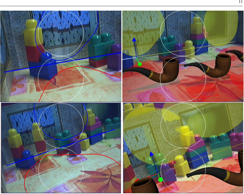
User input is performed using a hand-held camera and
four keyboard keys (the directional arrows). The camera-
mouse method is used to define the planar regions (called
2-D blobs) in the image stream. This method consists in se-
lecting objects by pointing at them through the camera. A
fixed cursor, generally a cross at the center of the camera
window, is used for ray-casting selection [2,12]. In our in-
terface, the cursor is not a cross but a circle and we do not
have one but two cursors (Fig. 7): one circle on the bottom
half of the screen is used to define 2-D blobs on the refer-
ence plane and another circle on the top half of the screen is
used to define 2-D blobs on the other planes. Pressing the up
or down key enables the operator to freeze the related cir-
cle into a blob which is immediately tracked in subsequent
frames using RANSAC matching of Harris corners
1
inside
the blob. Each time the user presses the key again, a convex
hull is computed between the tracked blob and the related
circle, forming a new blob which at its turn is tracked, and
so on, until the blob is fully defined.
Dierent tasks are performed during a working session
that are described below. In order to better understand how
things work in practice, the reader is invited to watch the
videos associated with this paper
2
.
Map initialization. Two blobs are indicated on non-parallel
planes using the camera-mouse. These blobs are tracked
while the camera is moved, and reconstructed in 3-D us-
ing the procedure described in section 4. Visual infor-
mation (intersection line between the planes, coordinate
system axes) are displayed on the video stream in order
to help the user to evaluate the accuracy of the solution
and decide to cancel or validate it.
1
Harris corners [10] are accurate, fast to compute and easy to match
between subsequent frames using cross-correlation.
2
http://www.loria.fr/˜gsimon/vc
Camera tracking. Once some 3-D blobs are available in
the map, multi-planar camera tracking can perform ac-
cording to section 5 and virtual objects can be added to
the scene.
Map expansion. At any time of the process, new 3-D blobs
can be added to the map using the camera-mouse. These
blobs can give rise to new planes or expand existing ones
(section 6).
Failure recovery. A procedure is used to recover from track-
ing failure, e.g. due to fast camera motion (section 7).
This procedure is based on SIFT feature matching
3
be-
tween a set of keyframes and the current frame. The
keyframes are stored during the working session upon
user request and each time a 3-D blob is added to the
map.
Bundle adjustment. A bundle adjustment of the position
and orientation of all the planes and keyviews in the map
can be requested at any time of the process, as described
in section 8.
Intersection lines with the reference plane play a cru-
cial role in this process. Given the correspondence of image
lines between a pair of images, the homographies induced
by planes containing the line in 3-space are reduced from a
3-parameter to a one-parameter family [24]. This property is
used there to get faster convergence and improved accuracy
during the map building steps. Moreover, intersection lines
provide visual hints that help the user to assess the accuracy
of the system-generated results and prevent map corruption.
4 Map Initialization
When two non-parallel planes are observed from two dif-
ferent views, closed-form solutions exist for computing the
equation of the planes as well as the camera motion between
the views [6,33]. However, the accuracy of these methods
is generally too poor for applications where the re-projected
structures have to be perfectly aligned with their image coun-
terpart. This is partly due to the fact that, although the same
camera motion is applied to the two planes, motion param-
eters are computed separately for each plane. Two solutions
are obtained, which are generally similar but not identical,
and one of these solutions has to be arbitrary chosen. It
is also not possible to integrate constraints such as fixing
the angle between the planes. For similar reasons, closed-
form solutions are not well adapted to handle more than
two views of the same planes. Closed-form solutions are
therefore mainly used as initial guesses to minimize the dif-
ference between some observed image points and their re-
3
SIFT features [21] are invariant to image scale and rotation and are
shown robust to some extend to ane distortion, change in viewpoint
and change to illumination. This makes them particularly suitable for
feature matching between distant images.

4
projections so that the estimation is optimized in the least-
square sense [33].
In [13], an extended Kalman filter (EKF) is used to cau-
sally estimate the camera motion, as well as the equation of
the planes related to some planar patches and the parameters
of an ane model used to handle the illumination changes
on the patches. However, Kalman filtering is sensitive both
to the initial values of the state vector and the tuning of the
first covariance matrices. Moreover, the size of the state vec-
tor is relatively high (18-parameters for two planes) due to
the fact that the planar patches are tracked inside the EKF
framework.
We propose to divide this computationally complex es-
timation problem into several simpler ones:
1. the planar surfaces are tracked independently between
the images, using RANSAC matching of Harris corners;
2. the projected intersection line between the observed pla-
nes (two parameters) is causally estimated using a par-
ticle filter (PF). PF has these advantages over EKF, that
it does not require any initial estimate of the state vec-
tor and it can handle non-linear measurement functions.
Moreover, the PF framework allows to easily fuse dif-
ferent kinds of likelihood measurements: in our case, a
geometric constraint imposed by the homographies and
a photometric constraint due to the specific appearance
of an intersection line in the image can be considered to-
gether, enhancing both the rate and the accuracy of the
detection;
3. the motion of the camera and the equation of the planes
in the 3-D Euclidean space are linearly approximated
and then iteratively refined using the Levenberg-Mar-
quardt optimization method. As the projection of the in-
tersection line in the first image is known, the equations
of the two planes can be expressed using 3 instead of
5 parameters. In addition to reducing the risk of being
trapped into a local minimum and shortening the pro-
cessing time of the iterative optimization, this simpler
parameterization allows to easily incorporate knowledge
on the angle between the planes.
Each stage of this algorithm is thus a rather simple task,
and an important point is that the intermediate results can be
assessed by the system or the operator before going to the
next stage:
tracking failures in stage 1 are automatically detected by
simply thresholding the number of inlier matches of the
homographies (see section 5),
the detected line of stage 2 can be visually assessed by
simple image comparison,
the 3-D reconstruction obtained at stage 3 can be visu-
ally assessed by displaying the world coordinate frame;
in order to facilitate this assessment, the origin of the
coordinate frame is put on the middle of the intersection
line and one of the three axes is aligned with that line.
Sections 4.1 and 4.2 now detail how the causal estima-
tion of the projected intersection line is performed, which is
a crucial stage of the algorithm; the Euclidean reconstruc-
tion of the scene - camera geometry based on the knowledge
of that line is then explained in section 4.3.
4.1 Preliminaries
We first set out some theoretical results that will be useful.
A plane projective transformation is a planar homology if it
has a line of fixed points (the axis), together with a fixed
point not on the line (the vertex) [14,11]. Algebraically, an
equivalent statement is that the 3 × 3 matrix representing the
transformation has two equal and one distinct eigenvalues.
The axis is the join of the eigenvectors corresponding to the
degenerate eigen-values. The third eigenvector corresponds
to the vertex.
Suppose we have two images, I
1
and I
2
, of a scene con-
sisting of two non-parallel planes, π
1
and π
2
. Let C
1
and C
2
be the positions of the camera center when I
1
and (resp.) I
2
were acquired. We further assume that the full-rank planar
homographies, H
1
and H
2
, induced by planes π
1
and (resp.)
π
2
between I
1
and I
2
are known.
Proposition 1. The 3 × 3 matrix S = H
1
2
H
1
is a planar
homology, whose axis is the projection l in I
1
of the intersec-
tion line between π
1
and π
2
and the vertex is the epipole e,
projection of C
2
in I
1
.
Proof Let us first prove that any point on line l is fixed by
S. Let p be a point on l. p is the projection in I
1
of a point P
on the intersection line between π
1
and π
2
. As P is on π
1
, p
is transformed by H
1
to the projection p
of P in I
2
. Now as
P is on π
2
, p
is transformed by H
1
2
to the projection p of P
in I
1
. This yields H
1
2
H
1
p p where denotes an equality
up to a scale factor.
Let us now prove that the epipole e is fixed by S. e is
the projection in I
1
of a point P
1
on π
1
. P
1
is the intersection
between π
1
and the ray passing though C
1
and C
2
. As C
1
,
C
2
and P
1
are aligned, the projection e
= H
1
e of P
1
in I
2
is the epipole in I
2
. Using the same reasoning but reversing
the roles of I
1
and I
2
, we prove that H
1
2
e
= H
1
2
H
1
e is the
epipole e in I
1
, which concludes the proof.
Corollary 1. The 3 × 3 matrix T = H
T
2
H
T
1
is a planar
homology, whose axis is a pencil of lines intersecting at the
epipole e and the vertex is the projection l of the intersection
line between π
1
and π
2
.

Citations
More filters
Journal ArticleDOI
TL;DR: A modular real-time diminished reality pipeline for indoor applications is presented, which includes a novel inpainting method which requires no prior information of the textures behind the object to be diminished.
Abstract: A modular real-time diminished reality pipeline for indoor applications is presented. The pipeline includes a novel inpainting method which requires no prior information of the textures behind the object to be diminished. The inpainting method operates on rectified images and adapts to scene illumination. In typically challenging illumination situations, the method produces more realistic results in indoor scenes than previous approaches. Modularity enables using alternative implementations in different stages and adapting the pipeline for different applications. Finally, practical solutions to problems occurring in diminished reality applications, for example interior design, are discussed.

42 citations


Cites methods from "Interactive building and augmentati..."

  • ...One possibility is to use floor plans or a 3D reconstruction system tomodel the room space, such as presented by Pintore and Gobbetti [22] or by Simon and Berger [27]....

    [...]

Dissertation
09 Dec 2019
TL;DR: Nous decrivons de plus une methode de modelisation in situ, qui permet d'obtenir de maniere fiable, de par leur confrontation immediate a the realite, des modeles 3D utiles au calcul de pose tel que nous l'envisageons.
Abstract: Mesurer en temps reel la pose d'une camera relativement a des reperes tridimensionnels identifies dans une image video est un, sinon le pilier fondamental de la realite augmentee. Nous proposons de resoudre ce probleme dans des environnements bâtis, a l'aide de la vision par ordinateur. Nous montrons qu'un systeme de positionnement plus precis que le GPS, et par ailleurs plus stable, plus rapide et moins couteux en memoire que d'autres systemes de positionnement visuel introduits dans la litterature, peut etre obtenu en faisant cooperer : approche probabiliste et geometrie aleatoire (detection a contrario des points de fuite de l'image), apprentissage profond (proposition de boites contenant des facades, elaboration d'un descripteur de facades base sur un reseau de neurones convolutifs), inference bayesienne (recalage par esperance-maximisation d'un modele geometrique et semantique compact des facades identifiees) et selection de modele (analyse des mouvements de la camera par suivi de plans textures). Nous decrivons de plus une methode de modelisation in situ, qui permet d'obtenir de maniere fiable, de par leur confrontation immediate a la realite, des modeles 3D utiles au calcul de pose tel que nous l'envisageons.

8 citations

Journal ArticleDOI
TL;DR: This work proposes an estimator based on a metaheuristic, the Teaching–Learning-Based Optimization algorithm (TLBO) that is motivated by the teaching–learning process and uses the TLBO algorithm in the problem of computing multiple view relations given by the homography and the fundamental matrix.
Abstract: In computer vision, estimating geometric relations between two different views of the same scene has great importance due to its applications in 3D reconstruction, object recognition and digitization, image registration, pose retrieval, visual tracking and more. The Random Sample Consensus (RANSAC) is the most popular heuristic technique to tackle this problem. However, RANSAC-like algorithms present a drawback regarding either the tuning of the number of samples and the threshold error or the computational burden. To relief this problem, we propose an estimator based on a metaheuristic, the Teaching–Learning-Based Optimization algorithm (TLBO) that is motivated by the teaching–learning process. We use the TLBO algorithm in the problem of computing multiple view relations given by the homography and the fundamental matrix. To improve the method, candidate models are better evaluated with a more precise objective function. To validate the efficacy of the proposed approach, several tests, and comparisons with two RANSAC-based algorithms and other metaheuristic-based estimators were executed.

3 citations

Book ChapterDOI
06 Dec 2013

2 citations

References
More filters
Journal ArticleDOI
TL;DR: This paper presents a method for extracting distinctive invariant features from images that can be used to perform reliable matching between different views of an object or scene and can robustly identify objects among clutter and occlusion while achieving near real-time performance.
Abstract: This paper presents a method for extracting distinctive invariant features from images that can be used to perform reliable matching between different views of an object or scene. The features are invariant to image scale and rotation, and are shown to provide robust matching across a substantial range of affine distortion, change in 3D viewpoint, addition of noise, and change in illumination. The features are highly distinctive, in the sense that a single feature can be correctly matched with high probability against a large database of features from many images. This paper also describes an approach to using these features for object recognition. The recognition proceeds by matching individual features to a database of features from known objects using a fast nearest-neighbor algorithm, followed by a Hough transform to identify clusters belonging to a single object, and finally performing verification through least-squares solution for consistent pose parameters. This approach to recognition can robustly identify objects among clutter and occlusion while achieving near real-time performance.

46,906 citations

Journal ArticleDOI
TL;DR: New results are derived on the minimum number of landmarks needed to obtain a solution, and algorithms are presented for computing these minimum-landmark solutions in closed form that provide the basis for an automatic system that can solve the Location Determination Problem under difficult viewing.
Abstract: A new paradigm, Random Sample Consensus (RANSAC), for fitting a model to experimental data is introduced. RANSAC is capable of interpreting/smoothing data containing a significant percentage of gross errors, and is thus ideally suited for applications in automated image analysis where interpretation is based on the data provided by error-prone feature detectors. A major portion of this paper describes the application of RANSAC to the Location Determination Problem (LDP): Given an image depicting a set of landmarks with known locations, determine that point in space from which the image was obtained. In response to a RANSAC requirement, new results are derived on the minimum number of landmarks needed to obtain a solution, and algorithms are presented for computing these minimum-landmark solutions in closed form. These results provide the basis for an automatic system that can solve the LDP under difficult viewing

23,396 citations

Book
01 Jan 2000
TL;DR: In this article, the authors provide comprehensive background material and explain how to apply the methods and implement the algorithms directly in a unified framework, including geometric principles and how to represent objects algebraically so they can be computed and applied.
Abstract: From the Publisher: A basic problem in computer vision is to understand the structure of a real world scene given several images of it. Recent major developments in the theory and practice of scene reconstruction are described in detail in a unified framework. The book covers the geometric principles and how to represent objects algebraically so they can be computed and applied. The authors provide comprehensive background material and explain how to apply the methods and implement the algorithms directly.

15,558 citations

01 Jan 2011
TL;DR: The Scale-Invariant Feature Transform (or SIFT) algorithm is a highly robust method to extract and consequently match distinctive invariant features from images that can then be used to reliably match objects in diering images.
Abstract: The Scale-Invariant Feature Transform (or SIFT) algorithm is a highly robust method to extract and consequently match distinctive invariant features from images. These features can then be used to reliably match objects in diering images. The algorithm was rst proposed by Lowe [12] and further developed to increase performance resulting in the classic paper [13] that served as foundation for SIFT which has played an important role in robotic and machine vision in the past decade.

14,708 citations


"Interactive building and augmentati..." refers background in this paper

  • ...3SIFT features [21] are invariant to image scale and rotation and are shown robust to some extend to affine distortion, change in viewpoint and change to illumination....

    [...]

01 Jan 2001
TL;DR: This book is referred to read because it is an inspiring book to give you more chance to get experiences and also thoughts and it will show the best book collections and completed collections.
Abstract: Downloading the book in this website lists can give you more advantages. It will show you the best book collections and completed collections. So many books can be found in this website. So, this is not only this multiple view geometry in computer vision. However, this book is referred to read because it is an inspiring book to give you more chance to get experiences and also thoughts. This is simple, read the soft file of the book and you get it.

14,282 citations


"Interactive building and augmentati..." refers background in this paper

  • ...This is algebraically expressed as [11]:...

    [...]

  • ...A plane projective transformation is a planar homology if it has a line of fixed points (the axis), together with a fixed point not on the line (the vertex) [11, 14]....

    [...]

Frequently Asked Questions (13)
Q1. What contributions have the authors mentioned in the paper "Interactive building and augmentation of piecewise planar environments using the intersection lines" ?

This paper describes a method for online interactive building of piecewise planar environments for immediate use in augmented reality. 

The authors presented a method for interactive building of multiplanar environments that has been validated on both synthetic and real data. The authors have shown the benefits of using semi-automatic rather than fully automatic algorithms for online building and augmenting of multiplanar scenes. When a lot of keyframes are available, this procedure may be time consuming. 

As d1 is an overall scale factor4, and as the authors can use ||n1|| = ||n2|| = 1, the authors have to estimate 11 parameters: 2 for π1, 3 for π2, 3 for R and 3 for t. 

The scale-dependent threshold problem may be tackled by segmenting planes into the 2-D video images instead of the 3-D point-cloud. 

For instance, in [17], user cooperation is used for initializing the map: when the system is started, the user places the camera above the workspace and presses a key to capture a first key-frame. 

Hz in tracking + filtering mode on a PC Dell Precision 390, 2.93 Ghz, while part of the processor was used to capture a video of the screen. 

A minimum requirement to be able to perform this task is that some planar surfaces are identified into the map upon which the virtual objects can be placed with correct orientation. 

Planar surfaces also make easy to handle self-occlusions of the map as well as collisions, occlusions, shadowing and reflections between the map and the added objects. 

As the projection of the intersection line in the first image is known, the equations of the two planes can be expressed using 3 instead of 5 parameters. 

The benefit of using semiautomatic, rather than fully automatic algorithms, is that the authors can model relevant structures for augmentation. 

their reconstruction procedure only depends on homographies which can be estimated from completely different sets of points matched between consecutive images. 

The key idea is to represent the required posterior density function p(xi|z1:i), where z1:i is the set of all available measurements up to time i, by a set of random samples x ji with associatedweights w ji , and to compute estimates based on these sam-ples and weights:p(xi|z1:i) ≈N ∑j=1w ji δ(xi − xj i ),N ∑j=1w ji = 1. 

The authors have shown the benefits of using semi-automatic rather than fully automatic algorithms for online building and augmenting of multiplanar scenes.