scispace - formally typeset
Search or ask a question
Journal ArticleDOI

Measurement of resistance curves in the longitudinal failure of composites using digital image correlation

TL;DR: In this paper, the authors presented a new methodology to measure the crack resistance curves associated with fiberdominated failure modes in polymer-matrix composites, which is based on the identification of the crack tip location using Digital Image Correlation and the calculation of the J-integral directly from the test data using a simple expression derived for cross-ply composite laminates.
About: This article is published in Composites Science and Technology.The article was published on 2010-11-15 and is currently open access. It has received 175 citations till now. The article focuses on the topics: Digital image correlation & Composite laminates.

Summary (2 min read)

1. Introduction

  • Sophisticated kinematic representations of failure mechanisms [8,9], and cohesive elements to deal with delamination [10,11], the accurate prediction of intralaminar fracture mechanisms still presents several challenges.
  • While this assumption is valid under smallscale bridging conditions, the shape of the cohesive law plays a fundamental role in the prediction of fracture under large-scale bridging conditions [12].
  • To account for these different failure mechanisms, a combined linear-exponential softening law for fiber tensile fracture has been proposed [5,6], and it was demonstrated that a simple linear softening law is unable to predict the load–displacement relation obtained in a cross-ply Compact Tension (CT) test specimen, while a bi-linear softening law provides an accurate prediction [13].
  • In addition, the experimental determination of the exact location of the tip of a kink-band is even more difficult than for the CT specimens.
  • An automatic algorithm that post-processes the full-field data provided by the DIC system during the CT and CC tests is used to detect the crack tip location and to establish the R-curve from the surface measurements of the displacement and strain fields.

2. Identification of the crack tip location

  • The algorithm used to identify the crack tip location in the CT and CC test specimens is based on the work of Grégoire [19].
  • The contour integral J, which is defined along a region where the material is linear-elastic, is therefore used to calculate the crack resistance curve of the CC and CT test specimens.
  • The same happens with the sum of the thicknesses of the all the 90 plies.
  • To simplify the calculations, the simple rectangular contour shown in Fig. 6 is selected.
  • The differentials dx1 and dx2 are taken as the differences between the centers of adjoining subsets, measured along the corresponding axes.

4.1. Configuration of the test specimens

  • The material used in this work is unidirectional carbon-fiber reinforced epoxy Hexcel IM7-8552.
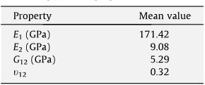
  • The elastic properties of IM7-8552, measured in a previous investigation [18], are shown in Table 1. E1 and E2 are the longitudinal and transverse.
  • The specimens were finally machined to their final geometry, shown in Fig. 7 (CT specimen), and in Fig. 8 (CC specimen).
  • In the set-up, the optical system was positioned perpendicular to the surface of the specimen mounted into the testing machine (Fig. 9).
  • The facet step (i.e., the distance between adjacent facets) can also be set either for controlling the total number of measuring points over the region of interest, or for enhancing the spatial resolution by slightly overlapping adjacent facets.

4.2. Compact tension

  • The load was measured using the 100 kN load cell, and the displacement was measured using the linear variable differential transformer (LVDT) connected to the hydraulic actuator of the test machine.
  • Fig. 12 shows a good correlation between the FEM and DIC data reduction methods.
  • This means that the fracture process zone that bridges the crack has a minor effect on the displacement and strain fields in the regions where the Finite Element model computes the J-integral.
  • Fig. 13 shows the R-curves obtained from the three CT tests.
  • Fig. 13 also shows the mean value of the fracture process zone, 3.4 mm, and the mean values of the initial fracture toughness and that corresponding to steady-state crack propagation, 97.8 kJ/m2 and 133.3 kJ/m2 respectively.

4.3. Compact compression

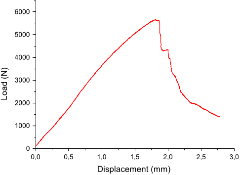
  • A non-linear response is observed in the load–displacement relation before the peak load is attained.
  • The reason for this fact is that the FEM-based calculation of the J-integral does not account for the contact and load transfer across the band of the kinked fibers.
  • On the other hand, the DIC-based method uses the actual displacement and strain fields on the surface of the specimen, provided that the contours selected do not include delaminated regions, thus resulting in an improved R-curve.
  • Delamination associated with the propagation of the kink-band from the initial notch was also observed in the CC tests.
  • In addition, the presence of delamination invalidates the assumption of a two-dimensional crack, and of constant strain through the thickness of the laminate (assumption used in Eq. (6)).

5. Conclusions

  • This paper presents a new method to measure the crack resistance curves in CT and CC test specimens manufactured using cross-ply CFRP composite laminates.
  • The method was implemented in a ”Matlab” code that obviates the need of any complex pre- and post-processing of the test data, either based on FEM or standard data reduction methods, and enables the real-time generation of R-curves during a test.
  • The mean value of the associated cohesive zone is 3.4 mm.
  • The DIC-based method is an improvement over FE-based data reduction methods because it is based on the actual displacement field on a pre-defined contour that does not include delaminated regions.
  • The values computed for the fracture toughness using the CC specimen do not account for the energy dissipated by the delamination that accompanied the propagation of the kink-band.

Did you find this useful? Give us your feedback

Citations
More filters
Journal ArticleDOI
TL;DR: DIC derived J-Integral is a reliable way to assess the fracture toughness of small sized specimens for dental CAD/CAM restorative materials; however, with caution applied to the selection of J-integral path.
Abstract: Ceramic and composite resin blocks for CAD/CAM machining of dental restorations are becoming more common. The sample sizes affordable by these blocks are smaller than ideal for stress intensity factor (SIF) based tests. The J-integral measurement calls for full field strain measurement, making it challenging to conduct. Accordingly, the J-integral values of dental restoration materials used in CAD/CAM restorations have not been reported to date. Digital image correlation (DIC) provides full field strain maps, making it possible to calculate the J-integral value. The aim of this study was to measure the J-integral value for CAD/CAM restorative materials. Four types of materials (sintered IPS E-MAX CAD, non-sintered IPS E-MAX CAD, Vita Mark II and Paradigm MZ100) were used to prepare beam samples for three-point bending tests. J-integrals were calculated for different integral path size and locations with respect to the crack tip. J-integral at path 1 for each material was 1.26±0.31×10(-4)MPam for MZ 100, 0.59±0.28×10(-4)MPam for sintered E-MAX, 0.19±0.07×10(-4)MPam for VM II, and 0.21±0.05×10(-4)MPam for non-sintered E-MAX. There were no significant differences between different integral path size, except for the non-sintered E-MAX group. J-integral paths of non-sintered E-MAX located within 42% of the height of the sample provided consistent values whereas outside this range resulted in lower J-integral values. Moreover, no significant difference was found among different integral path locations. The critical SIF was calculated from J-integral (KJ) along with geometry derived SIF values (KI). KI values were comparable with KJ and geometry based SIF values obtained from literature. Therefore, DIC derived J-integral is a reliable way to assess the fracture toughness of small sized specimens for dental CAD/CAM restorative materials; however, with caution applied to the selection of J-integral path.

11 citations

Journal ArticleDOI
TL;DR: In this paper, the authors evaluate the stress intensity factor in a double-edge cracked finite [013/905/013] graphite-epoxy orthotropic tensile composite from J-integral and a single digital image correlation recorded displacement field.

11 citations

Journal ArticleDOI
TL;DR: In this article, a cohesive zone model is used to model the material in a unidirectional carbon fiber composite that forms the kink-band, which is an important mechanism limiting the compressive strength of high strength composites.

10 citations

Journal ArticleDOI
TL;DR: In this article, the effects of the underlying micromechanisms were evaluated by employing experimental measurements of the fracture characteristics of fibers, matrices and fiber/matrix interfaces.
Abstract: The translaminar fracture behaviors of partially different unidirectional composite systems, constituted by the same carbon fibers but different (thermoset vs. thermoplastic) matrices, were characterized by means of compact tension fracture tests. The resulting crack resistance curves (R-curves) and fracture surfaces, were studied in detail and found to be rather different between those material systems, in spite of the same reinforcing fibers at similar volume fractions. In the attempt to justify this difference, the effects of the underlying micromechanisms were evaluated by employing experimental micromechanical measurements of the fracture characteristics of fibers, matrices and fiber/matrix interfaces. By means of a thorough analysis and quantification of the micromechanisms that contribute to the work of fracture, it was possible to decompose the translaminar fracture toughness of the composites into different contributions. Independently of the material considered, fibre bundle pull-out was found to be the mechanism that dissipates the highest amount of energy. Different patterns of bundle pull-out in different material systems were found to be the result of different outcomes from the competition of fracture micromechanims, and to be responsible for the differences between the translaminar fracture energies of both material systems. Moreover, it was realized that the energy dissipated in bundle pull-out, hence also the overall measured translaminar fracture toughness are strongly governed by in-situ effects, i.e. effects of specimen lamination features.

10 citations

Journal ArticleDOI
TL;DR: In this article, a mesoscale composites damage model for predicting the energy absorption capability of "tension-absorber" joints was developed and validated for use in future narrow-body composite fuselages.

10 citations


Cites background from "Measurement of resistance curves in..."

  • ...Table 6 IM7/8552 damage properties [24, 66, 72], for equations (15), (22), (23) and (25)...

    [...]

References
More filters
Journal ArticleDOI
James R. Rice1
TL;DR: In this paper, an integral is exhibited which has the same value for all paths surrounding a class of notches in two-dimensional deformation fields of linear or non-linear elastic materials.
Abstract: : An integral is exhibited which has the same value for all paths surrounding a class of notches in two-dimensional deformation fields of linear or non-linear elastic materials. The integral may be evaluated almost by inspection for a few notch configurations. Also, for materials of the elastic- plastic type (treated through a deformation rather than incremental formulation) , with a linear response to small stresses followed by non-linear yielding, the integral may be evaluated in terms of Irwin's stress intensity factor when yielding occurs on a scale small in comparison to notch size. On the other hand, the integral may be expressed in terms of the concentrated deformation field in the vicinity of the notch tip. This implies that some information on strain concentrations is obtainable without recourse to detailed non-linear analyses. Such an approach is exploited here. Applications are made to: Approximate estimates of strain concentrations at smooth ended notch tips in elastic and elastic-plastic materials, A general solution for crack tip separation in the Barenblatt-Dugdale crack model, leading to a proof of the identity of the Griffith theory and Barenblatt cohesive theory for elastic brittle fracture and to the inclusion of strain hardening behavior in the Dugdale model for plane stress yielding, and An approximate perfectly plastic plane strain analysis, based on the slip line theory, of contained plastic deformation at a crack tip and of crack blunting.

7,468 citations

Journal ArticleDOI
TL;DR: In this article, the authors proposed fracture analysis of structural members made of FRP composites and derived the fracture angle which is the key for this evaluation, which is derived in the present paper.

1,529 citations

Journal ArticleDOI
TL;DR: In this paper, a thermodynamically consistent damage model is proposed for the simulation of progressive delamination in composite materials under variable-mode ratio, and a constitutive equation is developed to model the initiation and propagation of delamination.

820 citations


"Measurement of resistance curves in..." refers background in this paper

  • ...Despite the significant advances in the analysis models for the prediction of fracture in composite materials such as advanced failure criteria and associated damage models [1–7], sophisticated kinematic representations of failure mechanisms [8,9], and cohesive elements to deal with delamination [10,11], the accurate prediction of intralaminar fracture mechanisms still presents several challenges....

    [...]

Journal ArticleDOI
TL;DR: In this article, an anisotropic damage model suitable for predicting failure and post-failure behavior in fiber-reinforced materials is presented, which is intended to predict behavior of elastic-brittle materials that show no significant plastic deformation before failure.
Abstract: This paper presents an anisotropic damage model suitable for predicting failure and post-failure behavior in fiber-reinforced materials. In the model the plane stress formulation is used and the response of the undamaged material is assumed to be linearly elastic. The model is intended to predict behavior of elastic-brittle materials that show no significant plastic deformation before failure. Four different failure modes – fiber tension, fiber compression, matrix tension, and matrix compression – are considered and modeled separately. The onset of damage is predicted using Hashin’s initiation criteria [Hashin Z, Rotem A. A fatigue failure criterion for fiber-reinforced materials. J Compos Mater 1973;7:448; Hashin Z. Failure criteria for unidirectional fiber composites. J Appl Mech 1980;47:329–34] and the progression of damage is controlled by a new damage evolution law, which is easy to implement in a finite element code. The evolution law is based on fracture energy dissipation during the damage process and the increase in damage is controlled by equivalent displacements. The issues related to numerical implementation, such as mesh sensitivity and convergence in the softening regime, are also addressed.

769 citations

Journal ArticleDOI
TL;DR: A continuum damage model for the prediction of the onset and evolution of intralaminar failure mechanisms and the collapse of structures manufactured in fiber-reinforced plastic laminates is proposed in this article.

686 citations


"Measurement of resistance curves in..." refers background in this paper

  • ...To account for these different failure mechanisms, a combined linear-exponential softening law for fiber tensile fracture has been proposed [5,6], and it was demonstrated that a simple linear softening law is unable to predict the load–displacement relation obtained in a cross-ply Compact Tension (CT) test specimen, while a bi-linear softening law provides an accurate prediction [13]....

    [...]

Frequently Asked Questions (1)
Q1. What are the contributions in "Measurement of resistance curves in the longitudinal failure of composites using digital image correlation" ?

This paper presents a new methodology to measure the crack resistance curves associated with fiberdominated failure modes in polymer–matrix composites.