
All figures (13)
 FIG. 8. X-ray diffractrograms showing the phase analysis of the converted layers on all four grades of cathodes.
 FIG. 7. (a)–(d) Images of all four grades of virgin (V) as well as worn (W) cathodes; (i)–(iv) are SEM micrographs showing the topography of all four grades of cathodes, the encircled regions in (iii) and (iv) host hole-like features; (v) represent the topography of 10 lm-grade cathode at low magnification indicating the extent of population density of hole-like features while (vi) the higher magnification of hole-like feature on 10 lm-grade cathode taken by tilting the stage at 45 ; this shows that multiple sub-holes reside in a hole-like feature.
 FIG. 14. Schema of the ejection mechanism of macro-particles from (a) a shallow crater, and (b) a deep and steep crater with the arrow representing the plasma pressure.
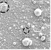 FIG. 10. SEM micrograph of the TiAl-N coatings (position 0 as shown in Fig. 2) deposited from (a) 1800 lmgrade, (b) 100 lm-grade, (c) 50 lmgrade and (d) 10 lm-grade; encircled regions in (a) and (d) denote flattened macro-particles.
 FIG. 1. (a) Schematic drawing of how a piece of Ti-50 at.% Al is glued to the surfaces of a dummy cathode. (b) Schematic drawing of the deposition geometry showing how the cathode, drum fixture, and the substrates were positioned (not to scale).
 FIG. 11. XRD diffractrograms of the coatings shown in Fig. 10; the measured residual stresses in the coatings are also stated along with the chemical composition.
 FIG. 12. Graphical representation of the variation of the thickness of the coatings, grown from all four grades of the cathodes, as a function of the angular distance of the substrates from the surface normal of the cathode; the corresponding vertical distance of the substrates on the drum fixture is also shown.
 FIG. 13. Graphical representation of the macro-particle areal density of the coatings deposited from all four grades of the cathodes as a function of angular distance of the substrates from the surface normal of the cathode; the corresponding vertical distance of the substrates on the drum fixture is also shown; the inset shows the re-scaled version of the macro-particle areal density of the coatings deposited by 100 lm-grade.
 FIG. 3. X-ray diffractograms of all four grades of virgin material.
 FIG. 2. SEM micrograph of virgin material (a) 1800lm-grade, (b) 100 lmgrade, (c) 50lm-grade, and (d) 10lmgrade.
 FIG. 4. SEM micrograph showing arc traces from a single trigger event on (a) polished 1800 lm-grade, (b) polished 100 lm-grade with an inset showing a magnified micrograph of Ti grain, (c) polished 50 lm-grade (* denote the regions of arced Al sandwiched between Ti grains), and (d) polished 10 lm-grade.
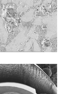 FIG. 5. (a) Scanning electron micrograph of macro-bubble with an EDX elemental map. (b) The excavation of macro-bubble achieved by Fib.
 FIG. 6. X-ray diffractograms of all four grades after a single trigger event.


