
All figures (13)
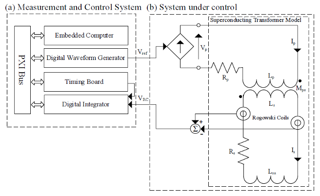 FIG. 2. Architecture of (a) measurement and control system, and (b) system under control.
 FIG. 5. Measurement and control setup.
 FIG. 9. Open-loop current cycles measured on the transformer secondary to assess the integration residual drift: (a) the whole cycles and (b) zoom on the end-cycles.
 FIG. 4. The sample insert (a) and the superconducting transformer (b) of FReSCa at CERN.
 FIG. 8. 1-σ repeatability (200 samples) of the system Rogowski coils-integrators at varying the current ramp rate.
 FIG. 12. Comparisons of U-I curves on a LHC cable of type 2 measured using the reference power supply and the superconducting transformer.
 FIG. 7. Set up for the measurement system characterization: (a) repeatability and (b) stability tests.
 FIG. 3. One-degree feedback controller for superconducting transformer.
 FIG. 1. Architecture of a transformer-based measurement station for superconducting cable test.
 FIG. 13. Long-term stability tests: current and voltage on the cable (a), and detail of voltage along current plateau (b).
 FIG. 11. Measured I*m and reference I * ref currents cycle at 20 kA (a), and differences between I * m and I * ref during ramp up (b1), and flattop with respect its average value (b2).
 FIG. 6. Frequency response bounds of the closed-loop transfer function (12), with ideal GT and τ, for a typical variation of +30 % of the transfer function parameters (left, magnitude, and, right, phase).
 FIG. 10. Example of reference current curve I*ref in controller assessment tests.


