scispace - formally typeset
Search or ask a question
Proceedings ArticleDOI

Periodic permanent magnet development for linear collider X-band klystrons

07 May 1999-Vol. 474, Iss: 1, pp 31-40
TL;DR: The Stanford Linear Accelerator Center (SLAC) klystron group is currently designing, fabricating and testing 11.424 GHz klystrons with peak output powers from 50 to 75 MW at 1 to 2 μs rf pulsewidths as part of an effort to realize components necessary for the construction of the Next Linear Collider (NLC) as mentioned in this paper.
Abstract: The Stanford Linear Accelerator Center (SLAC) klystron group is currently designing, fabricating and testing 11.424 GHz klystrons with peak output powers from 50 to 75 MW at 1 to 2 μs rf pulsewidths as part of an effort to realize components necessary for the construction of the Next Linear Collider (NLC). In order to eliminate the projected operational-year energy bill for klystron solenoids, Periodic Permanent Magnet (PPM) focusing has been employed on our latest X-band klystron designs. A PPM beam tester has operated at the same repetition rate, voltage and average beam power required for a 75-MW NLC klystron. Prototype 50 and 75-MW PPM klystrons were built and tested during 1996 and 1997 which operate from 50 to 70 MW at efficiencies greater than 55%. Construction and testing of 75-MW research klystrons will continue while the design and reliability is perfected. This paper will discuss the design of these PPM klystrons and the results of testing to date along with future plans for the development of a low-cost Design for Manufacture (DFM) 75-MW klystron and invitation for industry participation.

Summary (1 min read)

Jump to:  and [Summary]

Summary

  • Ultra wideband (UWB) is an upcoming standard for shortrange, high data rate communications link.
  • In order to minimize the power consumption, both operational transconductance amplifiers (OTAs) and filters need to be designed carefully.
  • The transconductance of the Nauta OTA is dependant on the supply voltage Vdd, which provides a means of tuning the filter.
  • Both inverter outputs contain non-linear square-law terms.
  • The design formulae for the filter can be attained by coefficient matching between (8) and (9) [12].
  • Using the computed parameter values in (10) and choosing identical transconductance of 1.5mS for gi (i=1,2…4) the capacitor values can be calculated, but the parasitic capacitance must also be taken into account.
  • Simulation results using 1.5V 0.18µm CMOS show that the power consumption of proposed filter is about 22.3mW at fc = 240MHz.

Did you find this useful? Give us your feedback
Content maybe subject to copyright    Report

SLAC-PUB-7925
September 1998
Presented at the XIX International Linac Conference (LINAC98), Chicago, August 23 - 28, 1998
PERIODIC PERMANENT MAGNET DEVELOPMENT FOR LINEAR
COLLIDER X-BAND KLYSTRONS
*
D. Sprehn, G. Caryotakis, E. Jongewaard and R. M. Phillips
Stanford Linear Accelerator Center
Stanford University, Stanford, CA 94309
*
This work is supported by the Department of
Energy under Contract DE-AC03-76SF00515
Abstract
The Stanford Linear Accelerator Center (SLAC)
klystron group is currently designing, fabricating and
testing 11.424 GHz klystrons with peak output powers
from 50 to 75 MW at 1 to 2 µs rf pulsewidths as part of an
effort to realize components necessary for the
construction of the Next Linear Collider (NLC). In order
to eliminate the projected operational-year energy bill for
klystron solenoids, Periodic Permanent Magnet (PPM)
focusing has been employed on our latest X-band klystron
designs. A PPM beam tester has operated at the same
repetition rate, voltage and average beam power required
for a 75 MW NLC klystron. Prototype 50 and 75 MW
PPM klystrons were built and tested during 1996 and
1997 which operate from 50 to 70 MW at efficiencies
greater than 55 %. Construction and testing of 75 MW
research klystrons will continue while the design and
reliability is perfected. This paper will discuss the design
of these PPM klystrons and the results of testing to date
along with future plans for the development of a low-cost
Design for Manufacture (DFM) 75 MW klystron and
invitation for industry participation.
1 AN INTRODUCTION TO PPM
Periodic Permanent Magnet (PPM) focusing is
utilized in Traveling-Wave Tube (TWT) devices for
commercial and military applications. Instead of a
solenoidal magnet with its associated overhead of power
supply, cooling, and controls, permanent magnets are
used to reduce operational cost and weight. In PPM
focusing the axial field changes polarity with every
magnet. If the magnetic period is small enough when
compared to the beam plasma wavelength, λp/L, then
sufficient beam stiffness can maintain the beam profile in
the presence of large space charge forces due to the rf
bunching.
Due to the high energy-products required for the
magnets combined with geometrical constraints, it is
usually not possible to thread as much flux through the
cathode as it is with solenoidal focusing so particular
attention must be paid to the gun design and beam
transport issues.
The ratio of the axial field to the Brillouin field,
Bz/Br, is shown in Table 1 along with other important
parameters for three SLAC solenoidal-focused klystrons
and three PPM designs. The Brillouin field is that value
of magnetic focusing at which all forces operating on the
beam are balanced and it is possible to transport the beam
with a constant radius. All of the klystrons have output
power levels from 50 to 75 MW except the 150 MW
DESY klystron. The cathode-to-beam area convergence,
A
c
, is approximately 100 for all the X-Band klystrons
because of the smaller drift tube dimensions. As can be
seen the B
z
/B
r
ratios for the PPM klystrons are not all that
different than those found for the solenoidal-focused
klystrons. The loss in axial beam velocity, u
z
, is higher
for the PPM klystrons due to the full reversal of the field
as seen by the beam.
Table 1: Comparison of SLAC Klystrons (see above text)
Tube 5045 Desy XL-4 50XP 75XP DFM
Beam Focusing Sol. Sol. Sol. PPM PPM PPM
frequency, GHz 2.86 3.00 11.42 11.42 11.42 11.42
Beam kV 350 525 440 464 490 490
uK 1.90 1.85 1.20 0.60 0.80 0.75
A
c
18 40 129 144 98 126
Cathode A/cm
2
6.34 5.04 8.75 7.39 7.71 7.23
B
z
confined, T 0.12 0.20 0.45 0.20 0.17 0.23
Flux cath/beam 0.85 0.94 0.92 0.50 0.55 0.75
B
z
/B
r
, axis
1.90 2.82 2.54 1.15 1.20 1.51
B
z
/B
r
, drift tube
1.90 2.82 2.54 2.03 2.11 2.66
u
z
0.1% 0.1% 0.1% 1.6% 2.5% 4.8%
The drawback with PPM focusing is that the
construction complexity of the tube may be increased so
construction costs and failure rates could rise. The
magnetic circuit is fixed and so there may be no easily
accessible "knob" for the operator to turn in case
adjustment is required. If the beam voltage is reduced
enough, λp/L becomes small and the beam will impact the
drift tube. This is known as the "stop-band" voltage.
Since the high voltage beam pulse has a finite rise and fall

time, then a portion of the beam pulse is below the stop-
band and interception occurs. There are also areas of
beam instability in PPM focused tubes and the possibility
of coupling to modes which grow from an undulating
beam.
2 PPM DEVELOPMENT PROGRAM
PPM focusing had never been used successfully on
very high-power klystrons and so there existed several
unknowns with respect to the outcome of such an attempt.
The large area beam convergence of 144:1, no axial field
adjustability, possible interactions with an undulating
beam, the presence of stop bands, and new materials and
construction techniques presented several engineering
challenges. It was decided to construct a beam-tester to
test the gun optics followed by a 50 MW klystron, and
lastly a 75 MW klystron. The 50 MW rf design was
patterned closely after the successful solenoid X-band
klystrons (XL series) at SLAC after allowances were
made to drop the perveance to improve efficiency. The
75 MW klystron design requires a slightly higher
perveance than the 50 MW design to keep the beam
voltage below 500 kV to reduce modulator costs.
The beam-tester and 50 MW klystron were
constructed with Samarium-Cobalt (SmCo) magnets and a
gun coil. These magnets were die-pressed individually
and a high level of quality control went into the
manufacturing process. Inspection of the field on the axis
agreed with simulation to within 1 %. To reduce cost, an
experiment was performed on the 75 MW klystron by
replacing the gun coil with permanent magnets and using
Neodymium-Iron-Boron (NdFeB) magnets instead of
SmCo. Replacing the gun coil forced large peak-to-peak
variations in the field strength design on axis, and
switching to bulk NdFeB resulted in a loss of control in
material quality. These magnets were fabricated out of
large blocks by slicing, core-drilling, and grinding to size.
Magnetic, on-axis, field strengths of the individual
magnets varied by as much as 20 % from simulation. The
75 MW design has more magnet periods in a plasma
wavelength and a higher focusing field to Brillouin field
ratio, both of which should allow for better focusing.
Design parameters for both the klystrons are found in
Table 2.
2.1 Beam-tester and 50 MW gun Design
In order to keep the cathode current density below an
average value of 7.5 A/cm
2
for increased lifetime, a 2.25"
diameter cathode was required which resulted in an area
convergence ratio of 144:1. Since this value is higher
than previous SLAC klystrons, a beam-tester was
fabricated to prove gun and drift region optics for the
PPM design. The design philosophy of the beam-tester
was to eliminate all sources of trouble that could interfere
with a study of the PPM beam formation and
transmission. The issues of gun voltage breakdown,
insufficient vacuum pumping, and collector power were
addressed by using oversized components from previous
klystron designs. This served to hasten the program and
allowed for operation at higher voltages than the design
required (in the interest of research into more powerful
PPM designs). Furthermore, it was decided to control
magnetic field in the gun with a standard bucking coil and
the field in the region from the gun to the beam minimum
with three compact coils closely wound around the drift
tube. The gun and magnetic circuit were constructed so
that operation with and without flux at the cathode was
possible. The same general philosophy and beam
focusing were used in the 50 MW klystron design.
Table 2: 11.424 GHz PPM klystron Specifications
rf power 50 MW 75 MW
Beam voltage 464 kV 490 kV
Beam current 190 A 257 A
rf pulsewidth
1.5µ
s @ 60Hz 1.5
µ
s @ 60Hz
Cathode loading
7.4 A/cm
2
7.2 A/cm
2
A
c
144:1 98:1
RMS Gauss 1950 1680
Efficiency 55 % 55 %
Gain 55 dB 55 dB
Max gradients:
Cavities
< 700 kV/cm < 650 kV/cm
Anode < 250 kV/cm < 250 kV/cm
Focus electrode < 220 kV/cm < 210 kV/cm
The drift tube is constructed of alternating iron pole
pieces and monel spacers that are brazed together in
subassemblies and then welded together at specially split
pole pieces. Each subassembly consists of eight
permanent magnets where each magnet produces an axial
field opposed in polarity to its immediate neighbor.
EGUN[1] simulations were performed (Fig. 1) until the
beam scalloping was less than 8 %. The testing began
with the confined flow case because the beam is held in
check by a larger magnetic field, and continued with the
shielded flow case afterward.
FIGURE 1. EGUN simulation of the beam as it enters the
PPM stack as used for the beam-tester and 50 MW
klystron.

When operated in the confined-flow condition the
high-convergence gun design has 50 % of the beam flux
threading the cathode (as measured at the axis). This is
low for typical high-power klystrons. Ratios for other
high-power klystron designs range from 80 to 95 %,
which yield 1.7 to 3.2 times the Brillouin field condition.
It is difficult to get large confinement ratios with PPM
focusing because the pole pieces eventually saturate and
magnetic materials have finite strengths. There also
exists a stability limit to the amount of field that may be
applied because the axial velocity is reduced due to the
large spin on the beam when the field is reversed from the
direction of the field in the cathode. A value of 50 %
yields 1.15 times the Brillouin field on the axis (Fig. 2)
which increases to 2 times at the drift tube. This is an
advantage because the further the beam strays from its
radial position, the more focusing force it experiences.
PPM focusing, as opposed to solenoidal focusing,
increases as distance from the axis increases, which leads
to a preference for focusing somewhat hollow beams. As
such, hollow beams are a direct result of the gun design
parameters in most high-power klystrons due to
limitations in the possible emission current density of
today’s cathode materials for long-life.
1.0
1.2
1.4
1.6
1.8
2.0
2.2
0.00 0.25 0.50
cm from axis
Bz / Br
FIGURE 2. Variation of RMS magnetic field vs. radial
distance from the axis for the PPM beam-tester and
50 MW PPM klystron.
0
1
2
3
4
20 60 100
Axial Position, (cm)
kGauss on axis
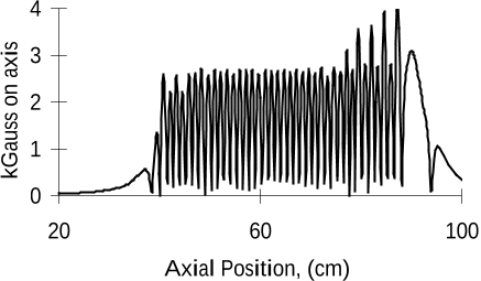
FIGURE 3. Axial field (Gauss) vs. axial distance (cm)
for the 50 MW PPM klystron.
The 50 MW PPM klystron rf design was based on the
highly successful XL-4 klystron development at SLAC.
The PPM klystron, with its lower perveance, lossy
materials, and higher operating voltage requires some
modifications in the existing XL-4 rf circuit design. The
rf circuit is adapted to the lower perveance beam by
increasing the cavity spacings, altering tunings, and
adding an extra cell in the traveling-wave output structure
for a total of 5 cells. The number of cavities was kept
constant and the bandwidth was reduced in order to
maintain the required gain. This loss in gain between the
two designs was primarily influenced by the lossy
materials used in the PPM design. The PPM cavities have
a lower Q
o
than copper cavities and therefore suffer more
rf heating. The lossy drift tube material may serve to
dampen possible trapped oscillations and any coupling
between the gun, cavities and collector. The magnetic
field is very similar to the beam-tester until the last three
cavities are reached where the field gradually tapers up to
eventually peak (Fig. 3) in the output structure. Tapering
serves to confine the beam as the space charge forces
increase due to the growing rf current. The field in the
output structure is unidirectional, unlike the rest of the
klystron where it is periodic, and this forces the magnets
to be larger.
2.2 Beam-tester and 50 MW Experimental
Results
The beam-tester processing began with a 1 µs beam
pulsewidth and proceeded up to 490 kV, 5 % above the
design point, without incident. The beam microperveance
was found to be 12 % higher than the design of 0.6 µK.
The reason for this discrepancy is not fully known,
although a full autopsy is scheduled to occur in October.
To improve the reliability of beam transmission data, the
pulse width was extended to 2.8 µs and the repetition rate
increased to 120 Hz. At 490 kV, there was roughly 42
kW dissipated in the collector. The beam transmission at
this point was found to be 99.9 %. This rather striking
result is in direct contrast to experience with travelling-
wave tubes (TWT) which traditionally are operated on a
bench and iron shunts are placed along the magnet circuit
to improve transmission. Such adjustments are not
possible with this high-power device as most of the tube
is covered in lead due to several kRads of radiation from
the collector.
No instabilities or spurious oscillations arising from
noise were detected at a 2.8 µs pulsewidth. No gas
pressure rise other than that considered normal was seen
and the collector vac-ion pump was running at about 10
-8
Torr under full power and rep rate. With a design goal for
the klystron of 1.5 µs and 465 kV, the operation of the
beam-tester exceeded expectations and demonstrated the
robustness of the design. The 490 kV level also happens
to be that which is required for the 75 MW X-band
klystron discussed later.
The three adjustment coils near the anode had
negligible effect on the transmission data but one of the
coils had a visible effect on the rising and falling edges of
the collector current pulse. Most importantly of all, the

shielded-gun operation and the confined-flow operation
were essentially identical. Thus the formation and
transport of the 144:1 area convergence beam into a
shielded or an immersed PPM-focused drift tube for a
high-power device has been proven feasible and robust.
Initial observations of the 50 MW klystron behavior
revealed that the gun behaved identically to the
beam-tester performance. An unusual gain curve
containing several jumps was believed to be due to
multipactor in more than one location in the drift tube
and/or cavities. The gain steps would decrease as beam
voltage, drive frequency, or bucking coil setting was
increased which means that the multipactor was not only
a function of the rf drive but also of the rf current present
on the beam and hence was located downstream of the
input cavity. To eliminate these discontinuities, the tube
was opened and the drift tube was coated with a titanium-
nitride (TiN) layer roughly 100 Å thick to reduce the
secondary emission coefficient of the surfaces subject to
rf fields in the vacuum. After testing a second time, only
one gain step remained.
Looking in the various coupling ports of the rf drive
and rf output, and with a small antenna probe at the
collector ceramic insulator, revealed no oscillations
higher than 50 dB below the fundamental, which can
easily be ignored. Small signal bandwidth was measured
at 40 MHz, which closely agrees with the predicted value
of 35 MHz. Measurements over a 70 dB range of rf drive
power showed the small signal gain to be 65 dB at the
design current, falling by 10 dB at the 50 MW power
level.
-500
-400
-300
-200
-100
0
-101234
Time, uS
kV, A, and MW
Vb
Ib
rf
FIGURE 4. 50 MW rf out, beam current (with and
without rf present), and beam voltage vs. time for the
50 MW PPM klystron.
After removing the gun coils, replacing the first eight
magnets, reducing the output magnet field, and applying
prefabricated shunts along the whole magnet stack, the
tube was tested in the shielded flow condition. The
klystron reached 50 MW with essentially the same gain
and efficiency with a 2 % increase in beam interception.
Despite the remaining step in the gain profile
(believed to be in the input cavity due to an insensitivity
to beam voltage) the PPM klystron reached the full
operational specification (Fig. 4) of 50 MW at 2 µs. The
efficiency at 50 MW was well over 55 %, and over 60 %
at 60 MW, using calorimetric diagnostics. The
intercepted beam power at 50 MW was about 1 % of the
total beam power, but the beam current lost about 7 %
while passing through the tube. This means that the
energy of the electrons lost in the tube must be about 66
keV on average.
2.3 A 75 MW Experimental Design
In designing the 75 MW klystron, major changes
made were enlarging the drift tube due to a higher beam
current, a stainless steel drift tube, and the elimination of
the gun focus coils. It was calculated that using a 5-cell
travelling-wave output circuit would extract more than
75 MW. Opening the beam tunnel by 13 % to 0.425
inches reduced the efficiency of the beam-cavity
interaction and thereby forced the inclusion of an extra
gain cavity. This also allows more modes to propagate
within the drift tube, including the second harmonic TM
mode. The construction of the 75 MW PPM magnetic
circuit differed in that the drift tube is a semi-continuous
stainless steel structure interrupted by the cavities, with
the iron pole pieces and non-magnetic spacers placed
outside the vacuum envelope. This design change
addresses three separate issues; avoiding the multipactor
seen in the 50 MW klystron, taking a step toward the
eventual low-cost design of a production klystron using a
clamp-on magnetic circuit, and adding loss in the drift
tube to increase the start-oscillation currents of the
various parasitic modes which may arise.
The large drift tube opening resulted in a lower beam
area convergence and lower current density in the beam,
which in turn reduced the necessary magnet strength. On
the other hand moving the pole pieces outside of the
vacuum envelope increased the magnet strength required
and the overall affect was a slightly higher energy-product
required for the 75 MW design. Previously, SmCo
magnets had been used that are highly resistant to
radiation and temperature. The 75 MW design used
NdFeB magnets which have higher energy-products, are
easier to machine, are less brittle, but have a lower Curie
temperature. However, at 500 keV photon levels,
radiation effects do not seem to be an issue over the
magnets projected lifetime. Furthermore, NdFeB magnets
are less expensive in bulk quantities. Procurement of the
NdFeB magnets presented many difficulties, as the
vendor was unable to meet the required specifications.
This material has been used in applications where the
absolute value of the magnetic energy-product is not
tightly held. This issue will be studied over the next few
months and a decision will be made on the magnetic
materials to be used in future designs.
Simulations of the klystron using CONDOR[2], a
2.5-D particle-in-cell code, show approximately 80 MW
at the design beam power while maintaining low gradients
in the output structure.

2.4 75 MW Experimental Results
Most of the completed magnets delivered to SLAC
failed to meet the specification. Specifically the magnets
at the beam convergence area near the gun, the gain
cavity magnets, the penultimate cavity magnet, and the
output magnets were all below specification. Due to time
constraints it was decided to test the klystron and testing
began with a 1 µs flattop beam pulse. Upon reaching 280
kV, an oscillation was noticed at the end of the beam
pulse. The beam pulse was reduced to zero flattop,
approximately 1 µs FWHM pulse, and the voltage was
raised to 360 kV until the oscillation was again seen. A
spectrum analyzer was used to carefully search for all
frequencies between 11 GHz and 26.6 GHz and found
only the fundamental, the second harmonic, and a signal
at 20 GHz.
As the beam voltage was increased the oscillation
could be damped by increases of the bucking coil, which
tends to make the beam smaller, but the method has the
limitation that too much of an increase and the beam
impacts unpredictably on the vacuum envelope.
Increasing the rf drive would also damp the oscillation but
overdriving most klystrons will usually produce another
set of instabilities. However, by combining the two
methods it was possible to raise the voltage peak to 463
kV and attain 71 MW peak at a 200 ns pulsewidth.
Despite the difficulties, gain was found to be between 55
and 60 dB and efficiency measured 60 % at the saturated
rf output level of 70 MW.
The magnets have been removed from the klystron
and are inserted on a full-scale model of the klystron
circuit so that the field can be shunted on the bench to a
desired profile. After simulation, theory, and
measurement agree on the required field, the newly
shunted stack will be installed on the klystron and testing
will resume. It is expected that this will occur late in
1998.
2.5 A Low Cost Klystron
A low-cost design of a 75 MW klystron known as the
Design For Manufacture klystron (DFM) has been under
investigation for the past three years and seeks to
minimize parts count, decrease complexity, reduce
construction labor, and increase reliability of the klystron.
A smaller gun and collector with reduced parts count,
better output waveguide hardware such as mode
converters and windows, and a simplified drift tube and
magnet structure are the main areas of scrutiny. Industry
participation will be solicited with several contracts
awarded to build 50 MW klystrons. Close cooperation
between industry and SLAC will be required for the
successful construction and operation of several thousand
75 MW PPM klystrons. One key to the lower cost will be
the development of a clamp-on magnet structure, which
can be used repeatedly as klystrons reach the end of their
useful lifetime. A clamp-on structure for evaluation
purposes is currently under fabrication at SLAC and will
be tested in the next few months.
Automated processing of the cathode activation, tube
bake and rf processing must be implemented in order to
keep up with the demand that will be an order of
magnitude greater than any similar effort to date. It is
currently planned that one or more factories on site will
continuously build and repair klystrons while the
accelerator is under construction and operation.
Eventually, the DFM klystron and the research
prototypes along with industry efforts will merge in a
single design using the best technologies from each.
CONCLUSIONS AND FUTURE WORK
The results of the 50 MW klystron testing exceeded
the design goals in terms of output power, pulsewidth and
efficiency, and provide a proof-of-principle for
high-power PPM klystrons. The magnetic field
difficulties with the 75 MW design can most likely be
overcome by returning to a magnetic circuit similar to the
50 MW klystron. Further study is required to fully
explore the failures and possible solutions concerning the
75 MW magnetic circuit. By early next year, a new design
will be tested which relies on lessons learned from the
previous 75 MW klystron. Furthermore, smaller gun and
collector designs, elimination of some vacuum pumps,
simpler output waveguide structures, and overall
cost-reduction schemes will continue development.
Despite the requirement for further engineering work,
this program has shown that a high-power PPM focused
klystron is not only feasible, but has demonstrated to
function in good agreement with simulation and
engineering analysis. The elimination of the focusing
solenoids for high-power accelerator sources is a major
cost reduction in both the procurement and operational
costs of such sources. It is likely that any future large-
scale, linear electron accelerator constructed will be
driven by PPM focused klystrons.
REFERENCES
[1] W. B. Herrmannsfeldt, "Electron trajectory program,"
SLAC 226, Stanford Linear Accelerator Center, Nov.
1979.
[2] B. Aimonetti, S. Brandon, K. Dyer, J. Moura, D.
Nielsen Jr., "CONDOR user’s guide," Livermore
Computing Systems Document, Lawrence Livermore
Nat’l Lab., April 1988.
Citations
More filters
Journal ArticleDOI
TL;DR: In this paper, a 3D model for the coupling of the lowest symmetric and asymmetric modes in a high-power, high-efficiency traveling-wave amplifier was developed.
Abstract: A three-dimensional (3-D) model has been developed for the investigation of the coupling of the lowest symmetric and asymmetric modes in a high-power, high-efficiency traveling-wave amplifier. We show that in a uniform structure and for an initially nonbunched beam, the interaction efficiency of the asymmetric mode may be much higher than that of the symmetric mode. It is also shown that the coupling between these two modes is determined by a single parameter that depends on the beam characteristics; its value varies between zero when no coupling exists and unity in case of maximum coupling. For a beam that is uniform at the input end, this parameter varies linearly with the guiding magnetic field. In case of a bunched beam, it decreases linearly with the increasing phase-spread of the bunch. Because of the interaction, the radius of the beam increases linearly with the power associated with the asymmetric mode at the input end; it increases rapidly in the case of an initially uniform beam relative to the case of a prebunched beam. Selective damping to suppress the asymmetric mode is described and analyzed.

20 citations

Journal ArticleDOI
TL;DR: A mechanism for electron beam halo formation is identified in high-power periodic permanent magnet (PPM) focusing klystron amplifiers in this paper, which is relevant to the development of high power microwave (HPM) sources and high-intensity electron and ion linear accelerators.
Abstract: Halo formation and control in space-charge-dominated electron and ion beams are investigated in parameter regimes relevant to the development of high-power microwave (HPM) sources and high-intensity electron and ion linear accelerators. In particular, a mechanism for electron beam halo formation is identified in high-power periodic permanent magnet (PPM) focusing klystron amplifiers. It is found in self-consistent simulations that large-amplitude current oscillations induce mismatched beam envelope oscillations and electron beam halo formation. Qualitative agreement is found between simulations and the 50 MW 11.4 GHz PPM focusing klystron experiment at Stanford Linear Accelerator Center (SLAC) (D. Sprehn, G. Caryotakis, E. Jongewaard, and R. M. Phillips, “Periodic permanent magnetic development for linear collider X-band klystrons,” Proceedings of the XIXth International Linac Conference, Argonne National Laboratory Report ANL-98/28, 1998, p. 689). Moreover, a new class of cold-fluid corkscrewing elliptic...

20 citations

Proceedings ArticleDOI
07 May 1999
TL;DR: In this article, a new approach to two-beam acceleration is discussed, where the energy for RF production is initially stored in a long-pulse electron beam which is efficiently accelerated to about 1.2 GeV by a fully loaded, conventional, low frequency (∼1 GHz) linac.
Abstract: In this paper we discuss a new approach to two-beam acceleration. The energy for RF production is initially stored in a long-pulse electron beam which is efficiently accelerated to about 1.2 GeV by a fully loaded, conventional, low frequency (∼1 GHz) linac. The beam pulse length is twice the length of the high-gradient linac. Segments of this long pulse beam are compressed using combiner rings to create a sequence of higher peak power drive beams with gaps in between. This train of drive beams is distributed from the end of the linac against the main beam direction down a common transport line so that each drive beam can power a section of the main linac. After a 180-degree turn, each high-current, low-energy drive beam is decelerated in low-impedance decelerator structures, and the resulting power is used to accelerate the low-current, high-energy beam in the main linac. The method discussed here seems relatively inexpensive, is very flexible and can be used to accelerate beams for linear colliders over the entire frequency and energy range.

13 citations

Journal ArticleDOI
TL;DR: In this paper, a two-dimensional self-consistent electrostatic model is used to analyze equilibrium beam transport in a periodic magnetic focusing field in the absence of a radio frequency (RF) signal.
Abstract: Electron beam halo formation is studied as a potential mechanism for electron beam losses in high-power periodic permanent magnet focusing klystron amplifiers. In particular, a two-dimensional (2-D) self-consistent electrostatic model is used to analyze equilibrium beam transport in a periodic magnetic focusing field in the absence of a radio frequency (RF) signal, and the behavior of a high-intensity electron beam under a current-oscillation-induced mismatch between the beam and the periodic magnetic focusing field. Detailed simulation results are presented for choices of system parameters corresponding to the 50-MW, 11.4-GHz periodic permanent magnet (PPM) focusing klystron experiment performed at the Stanford Linear Accelerator Center (SLAC). It is found from the self-consistent simulations that sizable halos appear after the beam envelope undergoes several oscillations, and that the residual magnetic field at the cathode plays an important role in delaying the halo formation process.

10 citations

Proceedings ArticleDOI
03 Jan 2006
TL;DR: In this article, the authors presented the first two X-band PPM klystrons for the Next Linear Collider (NLC) and tested them to the full NLC specifications of 75 MW, 1.6 microseconds pulse length, and 120 Hz.
Abstract: 75 MW X-band klystrons utilizing Periodic Permanent Magnet (PPM) focusing have been undergoing design, fabrication and testing at the Stanford Linear Accelerator Center (SLAC) for almost nine years. The klystron development has been geared toward realizing the necessary components for the construction of the Next Linear Collider (NLC). The PPM devices built to date which fit this class of operation consist of a variety of 50 MW and 75 MW devices constructed by SLAC, KEK (Tsukuba, Japan) and industry. All these tubes follow from the successful SLAC design of a 50 MW PPM klystron in 1996. In 2004 the latest two klystrons were constructed and tested with preliminary results reported at EPAC2004. The first of these two devices was tested to the full NLC specifications of 75 MW, 1.6 microseconds pulse length, and 120 Hz. This 14.4 kW average power operation came with a tube efficiency >50%. The most recent testing of these last two devices will be presented here. Design and manufacturing issues of the latest klystron, due to be tested by the Fall of 2005, are also discussed.

9 citations

References
More filters
ReportDOI
01 Nov 1979
TL;DR: The SLAC Electron Trajectory Program as mentioned in this paper is a program specifically written to compute trajectories of charged particles in electrostatic and magnetostatic focusing systems including the effects of space charge and self-magnetic fields.
Abstract: The SLAC Electron Trajectory Program is described and instructions and examples for users are given. The program is specifically written to compute trajectories of charged particles in electrostatic and magnetostatic focusing systems including the effects of space charge and self-magnetic fields. Starting options include Child's Law conditions on cathodes of various shapes. Either rectangular or cylindrically symmetric geometry may be used. Magntic fields may be specified using arbitrary configurations of coils, or the output of a magnet program such as Poisson or by an externally calculated array of the axial fields. The program is available in IBM FORTRAN but can be easily converted for use on other brands of hardware. The program is intended to be used with a plotter whose interface the user must provide.

246 citations


Additional excerpts

  • ...EGUN[1] simulations were performed (Fig....

    [...]

Frequently Asked Questions (16)
Q1. What are the contributions in "Periodic permanent magnet development for linear" ?

* This work is supported by the Department of Energy under Contract DE-AC03-76SF00515 Abstract The Stanford Linear Accelerator Center ( SLAC ) klystron group is currently designing, fabricating and testing 11. In order to eliminate the projected operational-year energy bill for klystron solenoids, Periodic Permanent Magnet ( PPM ) focusing has been employed on their latest X-band klystron designs. This paper will discuss the design of these PPM klystrons and the results of testing to date along with future plans for the development of a low-cost Design for Manufacture ( DFM ) 75 MW klystron and invitation for industry participation. 

The lossy drift tube material may serve to dampen possible trapped oscillations and any coupling between the gun, cavities and collector. 

The rf circuit is adapted to the lower perveance beam by increasing the cavity spacings, altering tunings, and adding an extra cell in the traveling-wave output structure for a total of 5 cells. 

There are also areas of beam instability in PPM focused tubes and the possibility of coupling to modes which grow from an undulating beam. 

Replacing the gun coil forced large peak-to-peak variations in the field strength design on axis, and switching to bulk NdFeB resulted in a loss of control in material quality. 

The beam-tester processing began with a 1 µs beam pulsewidth and proceeded up to 490 kV, 5 % above the design point, without incident. 

When operated in the confined-flow condition the high-convergence gun design has 50 % of the beam flux threading the cathode (as measured at the axis). 

The design philosophy of the beam-tester was to eliminate all sources of trouble that could interfere with a study of the PPM beam formation andtransmission. 

Periodic Permanent Magnet (PPM) focusing is utilized in Traveling-Wave Tube (TWT) devices for commercial and military applications. 

The three adjustment coils near the anode had negligible effect on the transmission data but one of the coils had a visible effect on the rising and falling edges of the collector current pulse. 

The drawback with PPM focusing is that the construction complexity of the tube may be increased so construction costs and failure rates could rise. 

As such, hollow beams are a direct result of the gun design parameters in most high-power klystrons due to limitations in the possible emission current density of today’s cathode materials for long-life. 

Due to the high energy-products required for the magnets combined with geometrical constraints, it is usually not possible to thread as much flux through the cathode as it is with solenoidal focusing so particular attention must be paid to the gun design and beam transport issues. 

Despite the difficulties, gain was found to be between 55 and 60 dB and efficiency measured 60 % at the saturated rf output level of 70 MW. 

It is difficult to get large confinement ratios with PPM focusing because the pole pieces eventually saturate and magnetic materials have finite strengths. 

Since the high voltage beam pulse has a finite rise and falltime, then a portion of the beam pulse is below the stopband and interception occurs.