
All figures (45)
 Fig. 3. Equivalent circuit of a PEMFC
 Fig. 3. Equivalent circuit of a PEMFC
![Fig. 10. Battery efficiency employed in the UPS system [17]](/figures/fig-10-battery-efficiency-employed-in-the-ups-system-17-22g6uqdq.png) Fig. 10. Battery efficiency employed in the UPS system [17]
Fig. 10. Battery efficiency employed in the UPS system [17] Fig. 4. Boundary conditions for macroscopic potentials in an SC
 Fig. 14. Voltages and currents waveform of PEMFC and SCs when FC charges SCs if SC voltage is
 Fig. 23. Power, current and efficiency characteristics of SC and UPS under the SC operating mode
 Fig. 22. Voltages and currents waveform of PEMFC operating mode when using the current
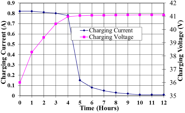 Fig. 11. Charging characteristics of SCs in this UPS system
 Fig. 12. PEMFC efficiency employed in the UPS system
![Fig. 10. Battery efficiency employed in the UPS system [17]](/figures/fig-10-battery-efficiency-employed-in-the-ups-system-17-1tdntydk.png) Fig. 10. Battery efficiency employed in the UPS system [17]
Fig. 10. Battery efficiency employed in the UPS system [17] Fig. 4. Boundary conditions for macroscopic potentials in an SC
 Fig. 15. Voltages and currents waveform of SC discharging when the main PEMFC fails
 Fig. 15. Voltages and currents waveform of SC discharging when the main PEMFC fails
 Fig. 19. Power, current and efficiency characteristics of UPS under the bypass operating mode
 Fig. 17. Photo of the experimental setup
 Fig. 14. Voltages and currents waveform of PEMFC and SCs when FC charges SCs if SC voltage is
 Fig. 18. Power, current and efficiency characteristics of UPS under the grid operating mode
 Fig. 18. Power, current and efficiency characteristics of UPS under the grid operating mode
 Fig. 23. Power, current and efficiency characteristics of SC and UPS under the SC operating mode
 Fig. 11. Charging characteristics of SCs in this UPS system
 Fig. 7. Equivalent circuit of a lead-acid battery
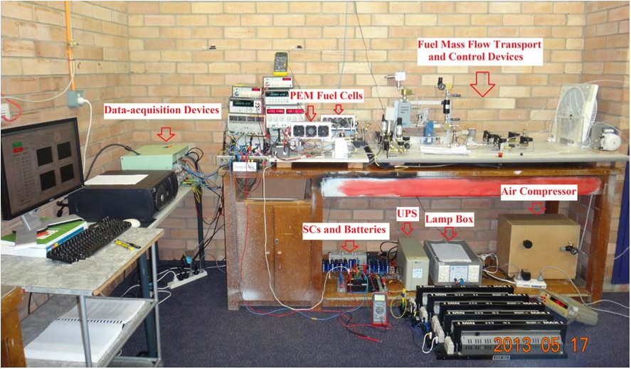 Fig. 17. Photo of the experimental setup
 Fig. 19. Power, current and efficiency characteristics of UPS under the bypass operating mode
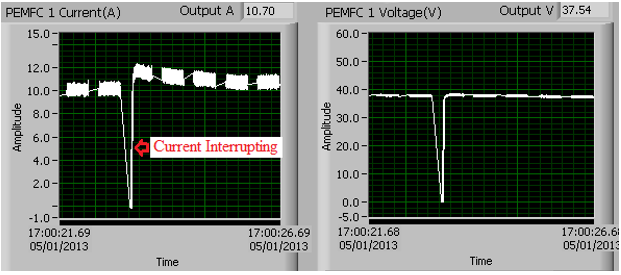 Fig. 22. Voltages and currents waveform of PEMFC operating mode when using the current
 Fig. 2. Proposed structure of grid/fuel cell/battery/SC hybrid power source in UPS application
 Fig. 6. Equivalent circuit of SC
 Fig. 12. PEMFC efficiency employed in the UPS system
 Fig. 7. Equivalent circuit of a lead-acid battery
 Fig. 20. Power, current and efficiency characteristics of battery and UPS under the battery operating
 Fig. 6. Equivalent circuit of SC
 Fig. 21. Power, current and efficiency characteristics of PEMFC and UPS under the FC operating
 Fig. 9. Four operating modes of the proposed UPS system with grid/PEMFC/battery/SC hybrid power sources
 Fig. 8. Equivalent circuit of SCs in parallel and in series
 Fig. 8. Equivalent circuit of SCs in parallel and in series
 Fig. 16. Voltages and currents waveform of battery discharging when main PEMFC fails
 Fig. 1. Traditional structure of PEM fuel cell/battery/SC hybrid power source
 Fig. 13. Charging characteristics of battery in UPS system
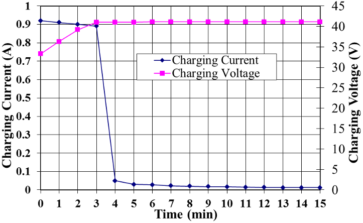 Fig. 13. Charging characteristics of battery in UPS system
 Fig. 16. Voltages and currents waveform of battery discharging when main PEMFC fails
 Fig. 21. Power, current and efficiency characteristics of PEMFC and UPS under the FC operating
 Fig. 9. Four operating modes of the proposed UPS system with grid/PEMFC/battery/SC hybrid power sources
 Fig. 1. Traditional structure of PEM fuel cell/battery/SC hybrid power source
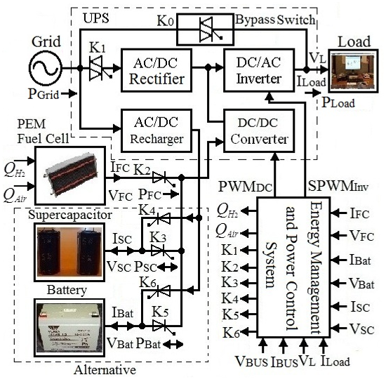 Fig. 2. Proposed structure of grid/fuel cell/battery/SC hybrid power source in UPS application
 Fig. 5. Transmission line equivalent circuit model of an SC
 Fig. 20. Power, current and efficiency characteristics of battery and UPS under the battery operating


![Fig. 10. Battery efficiency employed in the UPS system [17]](/figures/fig-10-battery-efficiency-employed-in-the-ups-system-17-22g6uqdq.webp)


![Fig. 10. Battery efficiency employed in the UPS system [17]](/figures/fig-10-battery-efficiency-employed-in-the-ups-system-17-1tdntydk.webp)


