scispace - formally typeset
Search or ask a question
Journal ArticleDOI

Target Location Using Dual-Beam Directional Modulated Circular Array

10 Sep 2018-IEEE Transactions on Antennas and Propagation (Institute of Electrical and Electronics Engineers Inc.)-Vol. 66, Iss: 12, pp 7525-7529
TL;DR: In this paper, a new concept directed toward the location of an object within a sector of space is introduced, by using a combination of the properties associated with directional modulation when implemented on a circular antenna array.
Abstract: A new concept directed toward the location of an object within a sector of space is introduced, by using a combination of the properties associated with directional modulation when implemented on a circular antenna array. In particular, we show that a circular antenna array can be made to project orthogonal data streams on orthogonal spatial beams and, through this process, create a temporal and spatial interference pattern that can be used for target location. This is demonstrated by the way of simulation of a two-beam 16-element circular antenna array carrying quadrature phase shift keying data.

Summary (2 min read)

Introduction

  • In particular, the authors show that a circular antenna array can be made to project orthogonal data streams on orthogonal spatial beams and through this process create a temporal and spatial interference pattern that can be used for target location.
  • I. INTRODUCTION Directional Modulation (DM), is a transmitter technology that is capable of projecting digitally modulated information signals into prespecified spatial directions while simultaneously distorting the constellation formats of the same signals in all other directions, [1].
  • This approach adds additional flexibility as well as grossly simplifying the practical arrangements in [2] for achieving the same result.
  • Section II describes the main properties of the circular array and the dual beam DM approach that are relevant to this paper.
  • Two cases are examined (i) symmetrical beam overlay and (ii) asymmetrical beam overlay.

A. General Circular Array Principle

  • Consider a multimode circular array consisting of 16 halfwavelength dipole antennas.
  • Manuscript received February 5, 2018, revised XXX, published XXX .
  • For any other purposes, permission must be obtained from the IEEE by emailing pubs-permissions@ieee.org.
  • (7) From which the QPSK symbol transmitted can be decoded at the receiver along an azimuthal direction ϕ.

III. SINGLE CYLINDER CIRCULAR ARRAY

  • In all other cases where FΣ(ϕ) ≠ FΔ(ϕ), consecutive symbols’.
  • Since any QPSK symbol is equally-likely the authors can predict the probability of bit error along ϕ by: Copyright (c) 2018 IEEE.
  • On the other hand, when this difference is not calibrated, it will eventually result in a high BER at ϕ = ˗18° and low BER point the azimuth direction ϕ = +18°, reducing two BER minima to one BER minima along the azimuthal angle (see Fig. 5(b)).

IV. EXPERIMENTAL RESULTS

  • To demonstrate the practical implementation of the proposed scheme, multimode circular array (MMCA) is fabricated and far field Copyright (c) 2018 IEEE.
  • For any other purposes, permission must be obtained from the IEEE by emailing pubs-permissions@ieee.org.
  • The dipoles are uniformly deployed and the separation angle between the consecutive dipoles is 22.5°.
  • These measured patterns are post processed to estimate the BER performance along the azimuthal direction.
  • In order to evaluate the impact of phase noise on the far field directivity, a simulation campaign was carried out based on the measured phase noise data.

V. TRACKING APPLICATION

  • If the transmitter and the receiver are co-located, then the values required for evaluation of (1) are available.
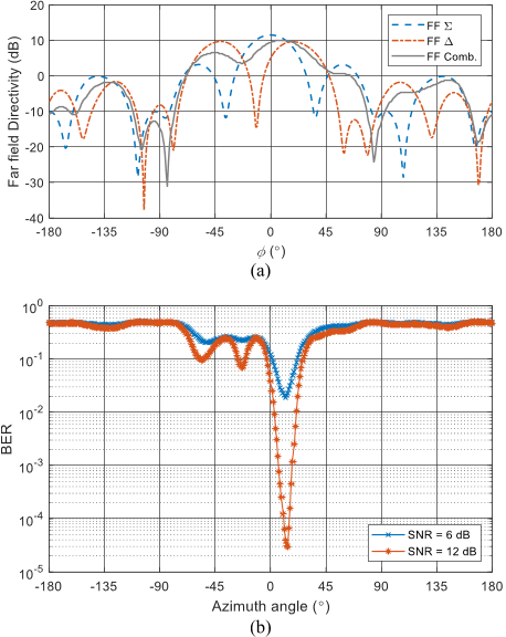
  • Expected received power is deducible from the transmitted FΣ(ϕ) and FΔ(ϕ) in Fig. 3(a), and can be used to evaluate constellation (Fig. 4) at an expected azimuthal direction ϕ.
  • This allows the possibility to track the location of the target as it moves in azimuth around the system permitting 360° coverage.
  • Here the difference pattern null is shifted to –12° the result of which is to significantly unbalance the DM in the –ϕ° direction while preserving the +ϕ° direction.
  • Following this, the sum pattern could be switched off, and the difference pattern null steered onto the target as this would yield better positional estimation since from Fig. 3 the difference pattern beam width at ˗20dB is < 5° while the asymmetrical BER BW is 11.5° for 10-3 BER.

VI. CONCLUSION

  • In this paper the authors show a new concept which relies on the concurrent multiple beam and beam rotation properties of a circular array coupled with the dual directional modulation coding scheme.
  • In this way the feasibility of tracking a non-cooperative target has been established.
  • The additional possibility of communicating with a suitable receiver equipped target was also described.

Did you find this useful? Give us your feedback

Content maybe subject to copyright    Report

Target Location Using Dual Beam Directional Modulated Circular
Array
Fusco, V., Chepala, A., & Abbasi, M. A. B. (2018). Target Location Using Dual Beam Directional Modulated
Circular Array.
IEEE Transactions on Antennas and Propagation
. https://doi.org/10.1109/TAP.2018.2869257
Published in:
IEEE Transactions on Antennas and Propagation
Document Version:
Peer reviewed version
Queen's University Belfast - Research Portal:
Link to publication record in Queen's University Belfast Research Portal
Publisher rights
© 2018 IEEE.
This work is made available online in accordance with the publisher’s policies. Please refer to any applicable terms of use of the publisher.
General rights
Copyright for the publications made accessible via the Queen's University Belfast Research Portal is retained by the author(s) and / or other
copyright owners and it is a condition of accessing these publications that users recognise and abide by the legal requirements associated
with these rights.
Take down policy
The Research Portal is Queen's institutional repository that provides access to Queen's research output. Every effort has been made to
ensure that content in the Research Portal does not infringe any person's rights, or applicable UK laws. If you discover content in the
Research Portal that you believe breaches copyright or violates any law, please contact openaccess@qub.ac.uk.
Download date:10. Aug. 2022

IEEE TRANSACTIONS ON ANTENNAS AND PROPAGATION
Target Location Using Dual Beam Directional Modulated Circular Array
Vincent Fusco, Anil Chepala, M. Ali Babar Abbasi
Abstract A new concept directed towards the location of an object
within a sector of space is introduced, by using a combination of the
properties associated with directional modulation when implemented on a
circular antenna array. In particular, we show that a circular antenna array
can be made to project orthogonal data streams on orthogonal spatial beams
and through this process create a temporal and spatial interference pattern
that can be used for target location. This is demonstrated by way of
simulation of a two beam sixteen element circular antenna array carrying
QPSK data.
Index Terms Circular array, directional modulation (DM), phase-
shift keying (PSK), physical-layer secure communication.
I. INTRODUCTION
Directional Modulation (DM), is a transmitter technology that is
capable of projecting digitally modulated information signals into pre-
specified spatial directions while simultaneously distorting the
constellation formats of the same signals in all other directions, [1].
Thus affording a level of physical layer security.
Fig. 1 shows a DM system modulated for quadrature phase-shift
keying (QPSK). From this figure it can be seen that the standard
formatted QPSK constellation patterns, in In-phase and Quadrature
(IQ) space, are not preserved along spatial directions away from the
pre-defined observation direction ϕ° (along azimuth plane), making it
difficult for potential eavesdroppers to intercept.
In [2] a DM method which mapped encoded orthogonal I, Q data
streams onto two different antenna far field patterns was given. This
method was called the dual-beam DM technique and allowed from a
knowledge of the two far field patterns projected from the array the
transmitted symbol sequence to be decoded only along the two pre-
defined directions where the two far field patterns have the same
magnitude response. It was shown in [3] that a circular antenna array
can be made to project multiple far field beam patterns when suitably
excited, for example using a Butler Matrix. This leads to the
interesting possibility that a circular antenna array can be made to
project the two orthogonal beams each of which can be separately
encoded. This approach adds additional flexibility as well as grossly
simplifying the practical arrangements in [2] for achieving the same
result. In addition, circular arrays have another very useful property.
Namely, by offsetting the phases applied to the Butler Matrix exciting
the circular array the resulting far field patterns can be made to rotate
through 360° in azimuth without the beam shapes distorting [4].
In this paper we show that by co-locating the transmitter and
receiver at the phase center of a circular array we can devise a radio
location strategy wherein bit error rate (BER) can be used as an
indicator of the presence of a target in a given sector of the radar’s
field of view, while preserving (i) the ability to track the target as it
moves in azimuth (ii) general target surveillance. Section II describes
the main properties of the circular array and the dual beam DM
approach that are relevant to this paper. Section III discusses the far
field radiation features based on numerical simulation results for an
example 16 element circular array. The resulting IQ spatial trajectory
loci and associated BER are also discussed from which target location
can be found. Two cases are examined (i) symmetrical beam overlay
and (ii) asymmetrical beam overlay. Section IV discusses the tracking
characteristics of the circular array based system when the transmitter
and the receiver are co-located at each array element, monostatic radar
fashion, while the findings are concluded in Section V of the paper.
II. GENERAL CIRCULAR ARRAY AND DUAL BEAM DIRECTIONAL
MODULATION PRINCIPLES
A. General Circular Array Principle
Consider a multimode circular array consisting of 16 half-
wavelength dipole antennas. The principle of operation of a
multimode circular array is most easily seen by considering a
continuous distribution of current, [5]. The horizontal far field
directional pattern F(ϕ)’ of a continuous circular aperture is a periodic
function with period 2π. Hence, it can, mathematically be expressed
as a complex Fourier series that is a function of both amplitude and
phase.
()
M
jm
m
mM
F C e

(1)
where
2
0
jm
m
C F e d

When ϕ = azimuth angle and m = mode number. Each of these
modes in equation (2) can be excited independently by using a Butler
Matrix (BM), [6].
Manuscript received February 5, 2018, revised XXX, published XXX
(projected). This work was supported by Queens’s University of Belfast
Studentship, and the UK Engineering and Physical Science Research Council
(EPSRC) under Grant EP/N020391/1.
V. Fusco, A. Chepala, and M. A. B. Abbasi are with The Centre for Wireless
Innovation (CWI), The Institute of Electronics, Communications and
Information Technology (ECIT), School of Electronics, Electrical Engineering
and Computer Science (EEECS), Queen's University Belfast, Belfast BT3
9DT, United Kingdom (email: v.fusco@ecit.qub.ac.uk,
achepala01@qub.ac.uk, m.abbasi@qub.ac.uk).
Color versions of one or more of the figures in this communication are
available online at http://ieeexplore.ieee.org.
Digital Object Identifier 10.1109/TAP.2018.xxx
QPSK DM
transmitter
Four Unique QPSK Symbols
Eavesdropper
I
Q
I
Q
ϕ
0
Eavesdropper
Assigned Receive Spatial Direction
ϕ
0
Legitimate Receiver
I
Q
Fig. 1. QPSK DM System Concept, [1].
This is the author's version of an article that has been published in this journal. Changes were made to this version by the publisher prior to publication.
The final version of record is available at http://dx.doi.org/10.1109/TAP.2018.2869257
Copyright (c) 2018 IEEE. Personal use is permitted. For any other purposes, permission must be obtained from the IEEE by emailing pubs-permissions@ieee.org.

IEEE TRANSACTIONS ON ANTENNAS AND PROPAGATION
If
K
j
K
Be
is the current applied to the Kth input port, the resultant
J
j
J
Ae
on the Jth radiating element is given by
2
K
J
jKJ
j
N
j
K
J
B e e
Ae
N



When many inputs are simultaneously excited then the output
current distribution is the summation over K for N element array. The
far field radiation pattern assuming the approximate pattern of dipole
A(ϕ) as 0.5×(1+cos(ϕ)) is given by
2 cos
J
K
jKJ N j r
j
KJ
JK
E B e e A e




When β = 2π/λ, λ is the wavelength of operation, and r is the radius
of the array, α
J
is a general representation of element angular location
in a circular array with N equally spaced elements at α
J
= J2π/N, when
J = 1,2, … N. Referring to the circular array center, the relative phase
of the Jth element in this case would be (2πr/λ) cos (ϕ - α
J
).
B Dual Beam Directional Modulation Principle
Far field patterns
Magnitude (dBi)
Phase (deg)
(a)
(b)
(c)
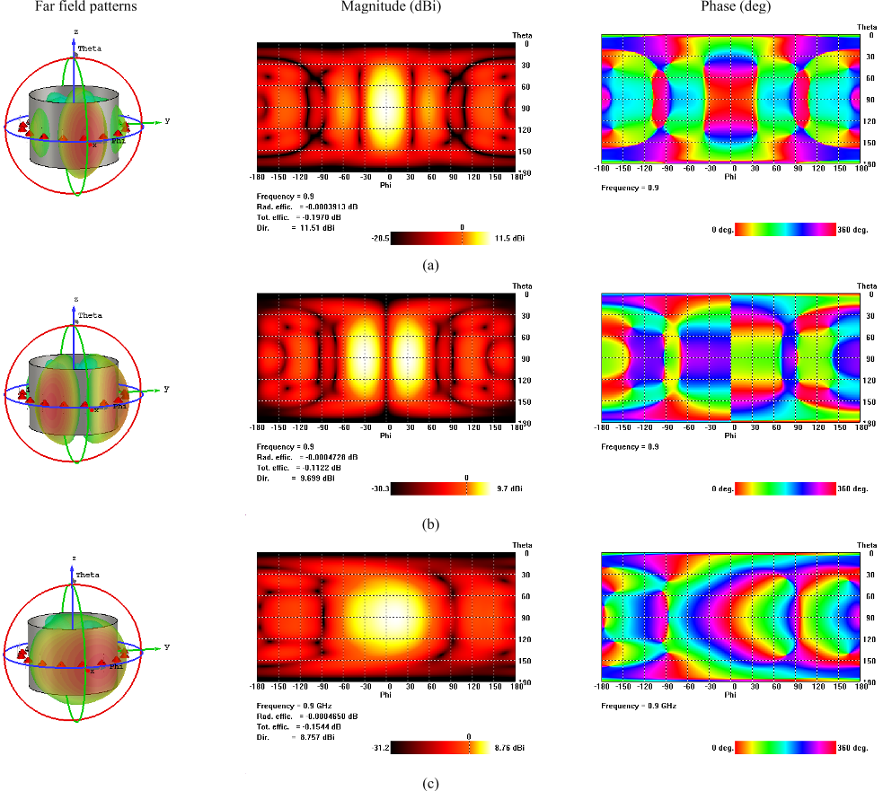
Fig. 2. (a) Sum (Σ), (b) Difference (Δ), and (c) Composite patterns of 16 element circular array at 900MHz. Far field patterns (left), magnitude (center), and
phase (right) are displayed column wise.
TABLE I
ANTENNA ELEMENT EXCITATION FOR Σ AND Δ FAR FIELD PATTERNS
Element index
1
2
3
4
5
6
7
8
9
10
11
12
13
14
15
16
|Σ|
0.979
0.666
0.642
0.365
0.227
0.389
0.279
0.339
0.279
0.389
0.227
0.365
0.642
0.666
0.979
1.852
Σ
38.6°
157.3°
-164.4°
-77.3°
-81.6°
-164.1°
-130.1°
-70.3°
-130.1°
-164.1°
-81.6°
-77.3°
-164.4°
157.3°
38.6°
23.2°
|Δ|
1.408
1.173
0.592
0.308
0.308
0.173
0.268
0
0.268
0.173
0.308
0.308
0.592
1.173
1.408
0
Δ
-73.7°
-56.3°
9.5°
33.4°
-83.3°
-58.7°
56°
52.7°
-124°
121.3°
96.7°
-146.6°
-170.5°
123.7°
106.3°
74.2°
This is the author's version of an article that has been published in this journal. Changes were made to this version by the publisher prior to publication.
The final version of record is available at http://dx.doi.org/10.1109/TAP.2018.2869257
Copyright (c) 2018 IEEE. Personal use is permitted. For any other purposes, permission must be obtained from the IEEE by emailing pubs-permissions@ieee.org.

IEEE TRANSACTIONS ON ANTENNAS AND PROPAGATION
In dual beam DM, [2], two excitation signals s
1
(t) = σ(t)×sinωt and
s
2
(t) = δ(t)×cosωt are used to encode two transmit beams F
Σ
(ϕ) and
F
Δ
(ϕ) , respectively, where σ(t) and δ(t) define the I and Q channel
data information, ω is the carrier frequency, and ϕ is the azimuth
angle of the receiver.
According to [2], the receive signal can be expressed as
1
2
,
( ) cos( ) ( ) sin( )
cos
jj
st
E t F e F e
st
t F t t F t
t








Here E(t, ϕ) is a complex digital symbol with a magnitude and a
phase that can be viewed as a constellation point on the real-imaginary
coordinate system. Φ is the calibrated RF phase delay defined as Φ =
Φ
Rx
+ Φ
Cal
+ Φ
Rot
. Here, Φ
Rx
is the instantaneous phase of an RF wave,
Φ
Cal
defines the azimuthal angle dependent phase calibration, while
Φ
Rot
is the phase calibration to prevent rotation of the received
constellation. Hence the magnitude and the phase of the receive signal,
are respectively,
22
FF

1
()
tan
()
tF
tF



From which the QPSK symbol transmitted can be decoded at the
receiver along an azimuthal direction ϕ. Target location using this
QPSK information is detailed in the proceeding sections.
III. SINGLE CYLINDER CIRCULAR ARRAY
Next we consider what happens when we project two orthogonal far
field patterns along direction ϕ. Sum and difference patterns are
respectively encoded with the orthogonal I and Q streams of a QPSK
symbol set. A Σ and Δ pattern can now be transmitted by the
multimode circular array sequentially. At the receive side, the
received signal can recreate the transmitted I and Q stream after phase
calibration. The sum pattern is characterized by a single main lobe
whose cross section is essentially elliptical, while the difference
pattern is characterized by a pair of main lobes of opposite phase
separated by a single null [7], [8]. The radius of the metal cylinder on
which the array is formed is 340 mm. The array has 16 equally spaced
half wavelength dipole elements, each tuned for 900MHz operation,
and positioned one-quarter wavelength above the metal cylinder at a
height of 83 mm. The array excitation matrix (output of BM) for sum
and difference patterns is tabulated in Table I when in addition to
mode 0, ±4 modes [5] (total 9) are excited. Fig. 2 shows the 3-D sum,
difference and composite far field patterns for the example case 16
Element Circular Array when operated at 900 MHz and with the beam
maximum for the sum pattern, and the beam null for the difference
pattern aligned along ϕ = 0°.
Fig. 2(b) and (c) presents 2-D representations of 3-D far field
patterns, here sum, difference and composite plots are shown from top
to bottom. A directive beam at ϕ = 0° is evident in the sum plot. Here
2-D contour color intensity represents gain value. Similarly, a far field
null at ϕ = spreading across the entire elevation plane can be seen
from the difference plot in Fig. 2(b). The corresponding phase shows
an abrupt discontinuity at ϕ = at the position of null. Fig. 3(c) shows
the resultant composite patterns for which array excitation is defined
as “Σ+Δ”. An unequal field distribution along ϕ and θ is evident from
Fig. 2(c). 1-D azimuthal cuts of 2-D far field plots are presented in
Fig. 3(a). Assuming ideal operation i.e. one in which noise and RF
delay are not considered, then at the receiver side, Fig. 3(b) presents
the IQ trajectory locus as a function of azimuth angle (ϕ). It is
interesting to note that the I Q points are located at different Euclidean
distances depending on the azimuth angle, as per (1). Since there are
two cross over points, in this case symmetrically positioned at ±18°,
these will be the spatial locations where the dual DM method will
yield the optimum direction for data recovery, i.e. the directions for
lowest BER. To further elaborate this, consider all four symbol states
of QPSK. Here the sum and difference far-field patterns at the receiver
end inherently contain all of the information required to evaluate Λ(ϕ).
On the other hand, Ψ(ϕ) depends not only on F
Σ
(ϕ) and F
Δ
(ϕ), but also
on the instantaneous phase of the received signal. In the absence of
noise and RF delay, Φ, when F
Σ
(ϕ) = F
Δ
(ϕ), respective symbols will
be located on a circle relatively at 0°, 90°, 180° or 270°. In all other
cases where F
Σ
(ϕ) F
Δ
(ϕ), consecutive symbols’ Euclidian distance
will disorder depending upon the power and the degree of the
difference between F
Σ
(ϕ) and F
Δ
(ϕ). This will have a direct impact on
BER. For the case presented in Fig. 3(a), F
Σ
(ϕ) = F
Δ
(ϕ) occurs at ϕ =
±18°, hence yielding the optimal azimuthal directions for best data
recovery. Based on the nearest-neighbor approximation of QPSK
constellation, the probability of symbol error rate in [9] is given by:
0
2
2
2
i
s
d
PQ
N




Where Q(x) is the complementary Gaussian error function, d
i
(i=1,2,3,4) is the minimum distance between two constellation points
and N
0
/2 is the noise power spectral density. Considering Gray coding
for the four constellation symbols, where each symbol represents two
bits, we know that P
b
P
s
/2. Since any QPSK symbol is equally-likely
we can predict the probability of bit error along ϕ by:
(a)
(b)
Fig. 3 (a) Azimuthal cut of far field patterns using Σ (main beam along ϕ = 0°),
Δ (null along ϕ = 0°) and resultant excitations for 16 element example array.
(b) Recovered IQ trajectory locus with azimuthal angle.
This is the author's version of an article that has been published in this journal. Changes were made to this version by the publisher prior to publication.
The final version of record is available at http://dx.doi.org/10.1109/TAP.2018.2869257
Copyright (c) 2018 IEEE. Personal use is permitted. For any other purposes, permission must be obtained from the IEEE by emailing pubs-permissions@ieee.org.

IEEE TRANSACTIONS ON ANTENNAS AND PROPAGATION
22
00
1
4
b
FF
P error Q Q
NN







Fig. 4 shows the situation when noise is added to the data. From this
it can be seen that, as expected, as SNR increases then the
constellations become better defined along the ±18° directions in this
case. Next we compute the BER for the system, here for example,
when SNR = 6dB and when SNR = 12dB as a function of azimuth
angle. A simulation campaign is carried out in which the circular
array, operating at 900 MHz, transmits a data stream of 10 million
ideal random bits, to ensure the simulated BER accuracy up to 10
-4
.
The results are presented in Fig. 5. The instantaneous phase of an RF
wave needs a re-calibration at the receiver end to form an un-rotated
constellation like the one presented in Fig. 4. Fig. 2(a) and (b) identify
an azimuth and elevation sector in which the phase of the RF wave is
almost the same. For both Σ and Δ patterns, the phase remains almost
constant within the elevation direction 6< θ < 120°. From Fig. 2(b),
if we compare the phases along the two azimuthal directions i.e. ˗180°
ϕ 0° and 0° < ϕ 180°, it can be seen that the two phases are 180°
apart. Fig. 5. shows that when this difference is calibrated, BER has a
clear spatial preference along the ±18° directions. (see Fig. 5(a)). On
the other hand, when this difference is not calibrated, it will eventually
result in a high BER at ϕ = ˗18° and low BER point the azimuth
direction ϕ = +18°, reducing two BER minima to one BER minima
along the azimuthal angle (see Fig. 5(b)). This is because of the fact
that for the azimuthal direction ˗180° ≤ ϕ ≤ 0°, the receiver will see a
180° rotation in the entire constellation when the complex digital
symbol E(t, ϕ) is constructed, eventually resulting in a high BER.
IV. EXPERIMENTAL RESULTS
To demonstrate the practical implementation of the proposed
scheme, multimode circular array (MMCA) is fabricated and far field
Fig. 4. Computed constellation diagrams under the presence of Noise at
multiple SNR levels along the azimuth direction ϕ = +18°.
(a)
(b)
Fig. 5. Computed BER as a function of azimuthal angle for symmetric Σ, and
Δ patterns in the (a) presence and the (b) absence of the phase calibration Φ
Cal
.
(a)
(b)
Fig. 6 (a) Fabricated MMCA and experimental setup photograph. (b)
Comparison between measured and simulated far field patterns along
azimuthal cut using Σ (main beam along ϕ = 0°) and Δ (null along ϕ = 0°)
excitations for 16 element example array.
Fig. 7. Comparison between BER as a function of azimuthal angle when BER
is computed based on the simulated and measured far field patterns.
Theoretical BER limit is defined by equation (9).
This is the author's version of an article that has been published in this journal. Changes were made to this version by the publisher prior to publication.
The final version of record is available at http://dx.doi.org/10.1109/TAP.2018.2869257
Copyright (c) 2018 IEEE. Personal use is permitted. For any other purposes, permission must be obtained from the IEEE by emailing pubs-permissions@ieee.org.

Citations
More filters
Proceedings Article
20 Jun 2019
TL;DR: In this paper, the first use of a circular array for retrodirection covering full 360° is presented, where the attributes of the circular array when combined with Rotman beam forming are discussed.
Abstract: We present the first use of a circular array for retrodirection covering full 360°. In particular, we discuss the attributes of the circular array when combined with Rotman beam forming. For reference the characteristics of the circular array when performing retrodirective action using local per element conjugation is also demonstrated. Simulated and measurement results at X-band are presented. The retrodirective circular array provides the advantage of 360° coverage when compared to other retrodirectors based on uniform linear arrays, as these typically allow only up to ±40° sector coverage.

3 citations


Cites background from "Target Location Using Dual-Beam Dir..."

  • ...When β = 2π/λ, λ is the wavelength of operation, and r is the radius of the array [4, 5], αJ is a general representation of element angular location in a circular array with N equally spaced elements at αJ = J2π/N, when J = 1,2, ....

    [...]

Journal ArticleDOI
TL;DR: In this article , a target location scheme for multi-target localization in free space is proposed, which exploits the properties of directional modulated antenna radiation patterns which are synthesized using time-modulated arrays (TMAs).
Abstract: In this paper, a target location scheme for multi-target localization in free space is proposed. It exploits the properties of directional modulated antenna radiation patterns which are synthesized using time-modulated arrays (TMAs). Here, we show that the TMAs can be made to synthesize directional modulation (DM) symbols concurrently upon multiple angular beams. Compared with previous DM works on target localization, our proposed system exhibits some promising features, such a ${i}$ ) generating multiple beams simultaneously, enabling multiple targets detection at the same time along different angular directions, ii ) allowing multiple access in frequency domain, iii ) requiring only one radio frequency (RF) chain with a signal peak- to-average power ratio (PAPR) of 0 dB; iv ) eliminating the azimuth ambiguity in mirror angular directions with respect to array boresight, ${v}$ ) flexibly adjusting the target angular resolution, and vi ) enabling beam steering without the need of phase shifters. The proposed technique is useful in various applications, such as tracking and controlling multiple drones, vehicles, and etc. It provides an alternative means in most of the Radar applications, and with the capability of wireless communication, it can be treated in the domain of waveform design for the Integrated Sensing and Communication (ISAC).

3 citations

DOI
TL;DR: It is shown that the TMAs can be made to synthesize directional modulation (DM) symbols concurrently upon multiple angular beams concurrently uponmultiple angular beams to exploit the properties of directional modulated antenna radiation patterns.
Abstract: In this paper, a target location scheme for multi-target localization in free space is proposed. It exploits the properties of directional modulated antenna radiation patterns which are synthesized using time-modulated arrays (TMAs). Here, we show that the TMAs can be made to synthesize directional modulation (DM) symbols concurrently upon multiple angular beams. Compared with previous DM works on target localization, our proposed system exhibits some promising features, such a ${i}$ ) generating multiple beams simultaneously, enabling multiple targets detection at the same time along different angular directions, ii) allowing multiple access in frequency domain, iii) requiring only one radio frequency (RF) chain with a signal peak- to-average power ratio (PAPR) of 0 dB; iv) eliminating the azimuth ambiguity in mirror angular directions with respect to array boresight, ${v}$ ) flexibly adjusting the target angular resolution, and vi) enabling beam steering without the need of phase shifters. The proposed technique is useful in various applications, such as tracking and controlling multiple drones, vehicles, and etc. It provides an alternative means in most of the Radar applications, and with the capability of wireless communication, it can be treated in the domain of waveform design for the Integrated Sensing and Communication (ISAC).

3 citations

Journal ArticleDOI
TL;DR: To find the field of view and analyze the NFDAM system, an analytical and straight forward approach for the radiation pattern and bit error rate spatial distribution is presented and an expression is also proposed for calculating the input impedance for each symbol.
Abstract: Full analysis with straight forward approach and a general procedure for designing the near-field direct antenna modulation (NFDAM) system is presented. In this paper, the required formulas are derived for calculating the Z-matrix elements of the NFDAM system and then, by using them, a set of switching combinations for the desired modulation is chosen. Also, to find the field of view and analyze the NFDAM system, an analytical and straight forward approach for the radiation pattern and bit error rate spatial distribution is presented. In addition, since the input impedance of the NFDAM system changes by changing the switching combination, an expression is also proposed for calculating the input impedance for each symbol. Furthermore, the design process and finally, two examples of designing the NFADM system are given. All calculated results are compared and validated with different simulations, to evaluate the proposed analysis and design. All simulations show the high accuracy of the proposed analysis.

1 citations

Journal ArticleDOI
TL;DR: In this paper , the authors proposed a hybrid beamforming antenna array structure based on a physical layer security technique called directional modulation (DM) for multi-beam multiplexing applications, where only one digital-to-analog converter (DAC) is connected to each subarray and finite-precision phase shifters are further considered.
Abstract: Abstract For integrated sensing and communication, one important research direction is to employ various beamforming techniques to avoid interference between the two functions. In this work, based on a hybrid beamforming antenna array structure, a physical layer security technique called directional modulation (DM) is studied for multi-beam multiplexing applications. The proposed design can form a more effective directional transmission through both beamforming and DM, while multiplexing multiple user beams through a common set of analog coefficients. In this hybrid beamforming structure, only one digital-to-analog converter (DAC) is connected to each subarray, and finite-precision phase shifters are further considered. Design examples for dual-beam multiplexing with an interleaved subarray structure and a localized subarray structure, respectively, are provided, which show that the interleaved subarray structure can form narrower mainlobe and a lower sidelobe level than the localized structure and has an overall better performance.
References
More filters
Book
01 Jan 2005

9,038 citations

Proceedings Article
01 Jan 2005
TL;DR: This book aims to provide a chronology of key events and individuals involved in the development of microelectronics technology over the past 50 years and some of the individuals involved have been identified and named.
Abstract: Alhussein Abouzeid Rensselaer Polytechnic Institute Raviraj Adve University of Toronto Dharma Agrawal University of Cincinnati Walid Ahmed Tyco M/A-COM Sonia Aissa University of Quebec, INRSEMT Huseyin Arslan University of South Florida Nallanathan Arumugam National University of Singapore Saewoong Bahk Seoul National University Claus Bauer Dolby Laboratories Brahim Bensaou Hong Kong University of Science and Technology Rick Blum Lehigh University Michael Buehrer Virginia Tech Antonio Capone Politecnico di Milano Javier Gómez Castellanos National University of Mexico Claude Castelluccia INRIA Henry Chan The Hong Kong Polytechnic University Ajit Chaturvedi Indian Institute of Technology Kanpur Jyh-Cheng Chen National Tsing Hua University Yong Huat Chew Institute for Infocomm Research Tricia Chigan Michigan Tech Dong-Ho Cho Korea Advanced Institute of Science and Tech. Jinho Choi University of New South Wales Carlos Cordeiro Philips Research USA Laurie Cuthbert Queen Mary University of London Arek Dadej University of South Australia Sajal Das University of Texas at Arlington Franco Davoli DIST University of Genoa Xiaodai Dong, University of Alberta Hassan El-sallabi Helsinki University of Technology Ozgur Ercetin Sabanci University Elza Erkip Polytechnic University Romano Fantacci University of Florence Frank Fitzek Aalborg University Mario Freire University of Beira Interior Vincent Gaudet University of Alberta Jairo Gutierrez University of Auckland Michael Hadjitheodosiou University of Maryland Zhu Han University of Maryland College Park Christian Hartmann Technische Universitat Munchen Hossam Hassanein Queen's University Soong Boon Hee Nanyang Technological University Paul Ho Simon Fraser University Antonio Iera University "Mediterranea" of Reggio Calabria Markku Juntti University of Oulu Stefan Kaiser DoCoMo Euro-Labs Nei Kato Tohoku University Dongkyun Kim Kyungpook National University Ryuji Kohno Yokohama National University Bhaskar Krishnamachari University of Southern California Giridhar Krishnamurthy Indian Institute of Technology Madras Lutz Lampe University of British Columbia Bjorn Landfeldt The University of Sydney Peter Langendoerfer IHP Microelectronics Technologies Eddie Law Ryerson University in Toronto

7,826 citations


"Target Location Using Dual-Beam Dir..." refers methods in this paper

  • ...Based on the nearest-neighbor approximation of QPSK constellation, the probability of symbol error rate in [9] is...

    [...]

Journal ArticleDOI
TL;DR: In order to formalize and extend on previous ad-hoc analysis and synthesis methods a theoretical treatment using vector representations of directional modulation systems is introduced and used to achieve DM transmitter characteristics.
Abstract: In order to formalize and extend on previous ad-hoc analysis and synthesis methods a theoretical treatment using vector representations of directional modulation (DM) systems is introduced and used to achieve DM transmitter characteristics. An orthogonal vector approach is proposed which allows the artificial orthogonal noise concept derived from information theory to be brought to bear on DM analysis and synthesis. The orthogonal vector method is validated and discussed via bit error rate (BER) simulations.

204 citations


"Target Location Using Dual-Beam Dir..." refers background in this paper

  • ...Directional modulation (DM) is a transmitter technology that is capable of projecting digitally modulated information signals into prespecified spatial directions, while simultaneously distorting the constellation formats of the same signals in all other directions [1]....

    [...]

Journal ArticleDOI

150 citations


"Target Location Using Dual-Beam Dir..." refers background in this paper

  • ...Each of these modes in (2) can be excited independently by using a BM [6]....

    [...]

Journal ArticleDOI
TL;DR: Simulation results show that this dual-beam DM technique offers a security transmission method for wireless communication.
Abstract: A dual-beam directional modulation (DM) technique is proposed for physical-layer secure communication. The main idea is that the in-phase and quadrature (IQ) baseband signals are used to excite two different antennas unlike a traditional transmitter, which is used to excite the same antenna. In this way, the constellation points of the transmit signal maintain their positions as traditional digital modulation signal at the desired direction, but scramble in the phase at the undesired directions because of the transmit signal both modulated at the baseband and the antenna level. Simulation results show that this dual-beam DM technique offers a security transmission method for wireless communication.

118 citations


"Target Location Using Dual-Beam Dir..." refers background or methods in this paper

  • ...This approach adds additional flexibility as well as grossly simplifying the practical arrangements in [2] for achieving the same result....

    [...]

  • ...In [2] a DM method which mapped encoded orthogonal I, Q data streams onto two different antenna far field patterns was given....

    [...]

  • ...According to [2], the receive signal can be expressed as...

    [...]

  • ...In dual beam DM, [2], two excitation signals s1(t) = σ(t)×sinωt and s2(t) = δ(t)×cosωt are used to encode two transmit beams FΣ(φ) and FΔ(φ) , respectively, where σ(t) and δ(t) define the I and Q channel data information, ω is the carrier frequency, and φ is the azimuth angle of the receiver....

    [...]

Frequently Asked Questions (2)
Q1. What contributions have the authors mentioned in the paper "Target location using dual beam directional modulated circular array" ?

A new concept directed towards the location of an object within a sector of space is introduced, by using a combination of the properties associated with directional modulation when implemented on a circular antenna array. In particular, the authors show that a circular antenna array can be made to project orthogonal data streams on orthogonal spatial beams and through this process create a temporal and spatial interference pattern that can be used for target location. 

The additional possibility of communicating with a suitable receiver equipped target was also described.