scispace - formally typeset
Open AccessJournal ArticleDOI

The skin-effect in ferromagnetic electrodes for wire-EDM

Reads0
Chats0
TLDR
In this article, the importance of the wire's impedance in wire electrical discharge machining has been shown, especially for ferromagnetic wires, such as steel wire, in terms of the work piece roughness and material integrity.
Abstract
In wire electrical discharge machining (wire-EDM) material is removed by the thermal energy of an electric spark that has been initiated between two electrodes (the wire and the workpiece), submerged in demineralised water. The use of high frequency current pulses for sparking leads to excellent machining performance, in terms of the work piece roughness, the material integrity of the cut and the material removal rate. To reach the highest frequencies, the wire-EDM generator mostly consists of a voltage source with an as low as possible internal inductance. The working current delivered to the spark and, hence, the material removal rate of the process depends on the total impedance of the electrical circuit. In this article the importance of the wire’s impedance will be shown. Due to the skin-effect, this impedance depends on the frequency of the current signal, especially for ferromagnetic wires, such as steel wire. Coatings will prove to be primordial to prevent the machining speed from dropping significantly.

read more

Content maybe subject to copyright    Report

The skin-effect in ferromagnetic electrodes for wire-EDM
B. Schacht
, J.-P. Kruth
, B. Lauwers
, P. Vanherck
Abstract
High frequency current pulses in wire-EDM lead to excellent machining performance, in
terms of work piece roughness, material integrity of the cut and material removal rate. To
reach the highest frequencies the wire-EDM generator mostly consists of a voltage source
with an as low as possible internal inductance. The working current delivered to the spark
and hence the material removal rate of the process depends on the total impedance of the
electrical circuit. In this article the importance of the wire’s impedance will be shown. Due
to the skin-effect this impedance depends on the frequency of the current signal, especially
for ferromagnetic wires, such as steel wire. Coatings will prove to be primordial to prevent
machining speed to drop significantly.
1 The high current needle-impulse generator
All modern wire EDmachines are equipped with a high current needle-impulse generator(figure 1)
[10]. It is able to deliver very short (0.2µs) and high current pulses (400A). The generator consists
of two independent voltage sources U
L
and U
H
. One is dedicated to deliver the ignition voltage
(U
H
) and current, the other must deliver a higher current (the working current) at lower voltage
(U
L
) necessary for material removal. The current of the first voltage source U
H
is limited to a few
(e.g. 16) Amperes, so that in fact it acts as a current source. In the spark’s ignition phase (1) S
2
and D
H
are engaged, after a while (2) the working current is imposed by engaging S
1
and S
2
. For
interrupting the spark (3), it is commuted to D
1
and D
2
. In this stage S
1
and S
2
are open. U
L
pulls the voltage down to enable a fast drop of the current. This excess of energy is stored in the
internal inductance of U
L
and used in the following spark.
A voltage source is chosen because it is more easy to produce steep current slopes (needle
impulse) with the latter source than with a current source. A needle-impulse generator minimizes
thermal influences on the work piece [1, 10]. On the other hand there is more electrode wear but
this is not so important in wire-EDM since the wire is continuously renewed. A voltage source
delivers a current that depends on the load: impedance of the machine, the wire, the gap and
the work piece, which is a disadvantage while compared to current sources, who are supposed to
deliver a fixed current independently of the process’s impedance. Two independent voltage sources
minimize energy loses in internal resistances. The current can reach 400A.
2 The skin-effect in ferromagnetic wire-electrodes
The skin-effect results from eddy currents within the wire that counteract the current in the core,
and forces the current to the surface of the wire. Figure 2 shows the resulting current density
distribution along the wire’s radius for a steel and a copper wire as it is simulated at 100kHz [7].
Generally speaking the current flows over a smaller area of the cross section of the wire due to the
skin-effect. It hence experiences higher resistance and lower inductance. For a steel wire of 250
µm diameter the current density J at the surface of the wire is almost 500 times as big as on the
axis. For a copper wire it is only 1% bigger. The following subsections will discuss the frequency
and material dependence of both.
Katholieke Universiteit Leuven, Division PMA, Celestijnenlaan 300B, 3001 Leuven, Bel-
gium
1

U
L
U
H
R
H
R
W
L
S
D
H
D
2
D
1
S
1
S
2
i
I(t)
t
t
U(t)
td tdte to te
Figure 1: Principle scheme of the high current needle-impulse generator
Steel wire
Wire radius r (µm)
Current density ratio j(r)/j(0)
Wire radius r (µm)
Copper wire
1
Figure 2: Effect of skin-effect on current density distribution at 100kHz
2

Steel 0.05% C Steel 0.7% C Copper Brass CuZn
37
ν(Hz) 100000 100000 100000 100000
σ
¡
S
m
¢
7.7e
6
5.6e
6
5.7e
7
1.5e
7
µ
r
5000 4000 1 1
diameter (µm) 100 250 100 250 100 250 100 250
ξ 3.08 7.70 2.35 5.87 0.12 0.29 0.06 0.15
R
0
¡
m
¢
16.53 2.64 22.73 3.63 2.23 0.36 8.48 1.35
R
¡
m
¢
55.21 21.01 59.55 22.25 2.23 0.36 8.48 1.35
R
R
0
3.34 7.96 2.62 6.13 1 1.003 1 1.0002
L
0
µH
m
200 200 250 250 0.05 0.05 0.05 0.05
L
µH
m
80 32 84 34 0.05 0.05 0.05 0.05
L
L
0
0.16 0.13 0.59 0.24 1 1 1 1
Table 1: mathematical values related to the skin-effect in plain wires
2.1 The frequency dependence of a wire’s resistance
2.1.1 Plain wires
The frequency dependence of a wire’s resistance is approximately given in [4] by
R
R
0
1 +
ξ
4
3
if ξ << 1
R
R
0
1
4
+ ξ +
3
64ξ
if ξ >> 1 (1)
The value ξ (given by equation 2) indicates whether the skin-effect is important for the wire
under consideration. This depends on its radius r
0
, its electrical conductivity σ, its magnetic
permeability µ and the frequency of the current signal ν.
ξ =
r
0
2
πνσµ (2)
R
0
is the D.C. resistance per unit length of the wire and is given by Pouillet’s formula as
R
0
=
1
πσr
2
0
(3)
The value of equations 1, 2 and 3 is calculated for steel and copper wires of diameter 100 and
250µm at 100kHz. This is the ground frequency of the current signal. The results are given
in table 2.1.1. It shows that the skin-effect only plays an important role for steel wires, and
especially for steel wires with big diameter. The reason for the presence of this effect in steel wires
is their high magnetic permeability. The result is an increased resistance. For wires of 250µm the
resistance goes up by a factor 6 to 8, depending on the carbon content of the wire. Interesting
to see is that the lower carbon content steel wire has a lower resistance at D.C., but at high
frequencies it rises to the same level as the higher resistant high carbon content wire. This can
be fully explained by equation 2: the importance of the skin-effect rises with conductivity and
permeability. The resulting resistance for steel wires at 100kHz is 60 times as high as for copper.
For the steel wire of diameter 100µm the influence of the skin-effect is less, it yields an increase
of the resistance by a factor 2 to 3, resulting in a value which is 30 times as high as a copper wire.
Since the resistance of a steel wire at the frequencies under consideration seems to be independent
of carbon content, the 0.7%C wire can be chosen to profit from its higher tensile strength in
precision applications [6, 8].
2.1.2 Coated wires
The influence of the skin-effect on the overall resistance of a steel wire can be minimized by
introducing non-magnetic-permeable materials in the coating that are good conductors. Of course
3

Name Core Subcoating Coating R
0
R R/R
0
thickness (µm) thickness (µm) thickness (µm) (Ω/m) (Ω/m)
Macrocut Steel 0.64% C CuZn42 Ag 2.364 3.485 1.47
102.9 22 0.1
Compeed Steel 0.075% C Cu CuZn43 0.977 1.105 1.13
97 20 8
E
0/1
Steel 0.7% C None Zn 3.523 17.322 4.91
124 0 1
E
0/10
Steel 0.7% C None Zn 2.771 5.908 2.13
115 0 10
E
10/1
Steel 0.7% C Cu Zn 1.496 2.082 1.39
114 10 1
E
10/10
Steel 0.7% C Cu Zn 1.396 1.787 1.28
105 10 10
Table 2: mathematical values related to the skin-effect in coated wires
in this case the D.C. resistance will be lowered, but furthermore at high frequencies the raising of
the resistance will be damped. The current that is forced out of the core will chose the path of
least resistance and will be conducted in the coating.
Since all known coatings (Cu, CuZn
x
, Zn,...) are a-magnetic, the skin-effect can be neglected
in the calculation of the resistance of the coating. For a coating with outer radius r
o
and inner
radius r
i
it is given by
R
coating
=
1
σ
coating
π(r
2
o
r
2
i
)
(4)
The total value of the wire’s resistance is then found by assuming that the core of the wire is
electrically parallel to the coating. For a steel wire the resistance of the core and hence of the
whole wire is frequency dependent. It is calculated according to section 2.1.1 For coated brass or
copper wires there is no dependency at the frequency under investigation (ν = 100kHz). Table
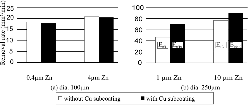
2.1.2 summarizes the obtained values for some commercial and some experimental diameter 250µm
steel wires.
The table shows first of all that the D.C-resistance of the coated wires is smaller because of the
good conductive coating that is electrically in parallel, but secondly the rising of the resistance
is less compared to plain wires (table 2.1.1). For thick coatings the D.C. as well as the high
frequency resistances are comparable to those of plain brass wires, while the tensile strength of
their cores stays considerably higher. For wires of smaller diameter, e.g. 100 µm, this will be valid
to a lesser extent, because the increase in resistance due to the skin-effect is smaller in absolute
numbers (table 2.1.1). Relatively speaking it is even smaller compared to the D.C. resistance.
Because of the smaller diameter this is already one order of magnitude higher compared to 250
µm wires (equation 3). Moreover the coating’s cross sectional area is relatively smaller too. In
this sense the resistance electrically parallel to the steel core is smaller and less able to lower the
total resistance of the wire. When calculated for a steel wire (0.7%C) with a 4 µm Zn-coating
the D.C. resistance is 17.32 /m, compared to 22.73 /m without coating. It increases to 24.27
/m at 100kHz. This is a factor 1.4 compared to 2.62 without coating. For even thinner wires
the influence of the skin-effect and the conductive properties of the coating drops further.
E
x/y
= Steel 0.7%C core with x µm Cu and y µm Zn.
4

2.2 The frequency dependence of a wire’s inductance
2.2.1 Plain wires
The frequency dependence of a wire’s internal inductance is approximately given by equation 5,
with ξ given by equation 2.
2πνL
R
0
ξ
2
ξ
6
6
if ξ << 1
2πνL
R
0
ξ
3
64ξ
+
3
128ξ
3
if ξ >> 1 (5)
The wire’s inductance L
0
at low frequencies equals
µ
8π
[7]. The calculated values are given in
table 2.1.1. Again there is no noticeable effect of frequency on the inductance of a copper or brass
wire, there is however an effect on the inductance of a steel wire. With increasing frequency the
inductance decreases by 40% for a 100µm steel wire and 75% for a 250µm steel wire. This effect is
hence advantageous for the use of the high current needle-impulse generator (discussed in section
1 and [10]), but still the inductance of steel wire remains three orders of magnitude higher than
e.g. the inductance of a brass wire.
It should be noted that in this section only the internal inductance of the wire was calculated.
The magnetic energy stored in the field outside the wire was disregarded. The total inductance is
very difficult to calculate, since the geometry of the work piece and the work piece material must
be taken into account. The total inductance of the circuit excluding the wire is estimated to be
in the order of magnitude of 400nH. However, since this paper only aims at comparing different
wires, the testing conditions are chosen in such a manner that only the internal inductance is
variable. This is achieved by fixing the work piece geometry and material (in this case ohler
K107 steel (DIN X210CrW12) of 30 mm height).
2.2.2 Coated wires
The internal inductance of a coated a-magnetic wire can be calculated by calculating the energy
stored in the magnetic field inside the wire. It is possible to do this for coated a-magnetic wires
but it is rather difficult to calculate inductance values for coated steel wires at high frequencies.
A simple decomposition into parallel inductances, analogous to the calculation of the resistance,
is not valid. Mutual induction is here to be taken into account. An attempt is made in [7]
using energetic considerations. Appropriate conclusions can however also be made from physical
insights.
The dropping of the inductance due to the skin-effect in steel wires, as explained in section
2.2.1, will be counteracted by using a thin conductive coating which is non-permeable (copper,
brass, zinc, . . . ) in the same way the rising of the resistance in counteracted. After all the steel
core is thinner, if a coating is used, and hence less subjected to the skin-effect.
When the coating becomes thick on the other hand the inductance will again be lowered. Most
of the current will flow in this non-permeable high conductive coating, which is electrically parallel
to the steel core. It will hence see a low inductance. The thicker the coating becomes, the closer
the inductance will come to that of a plain wire made out of the coating material. As shown
in table 2.1.1, the inductance of plain wires of these materials is much lower. The use of thick
coatings on steel wires is hence good for lowering the inductive load on the generator.
3 Influence of wire impedance on the process’s performance
The wire impedance is immediately reflected in the working current and the attained surface
roughness of the work piece. A less correlation is found to the material removal rate.
5

Citations
More filters
Journal ArticleDOI

Effect of Electrode Size on the Performances of Micro-EDM

TL;DR: In this article, the effect of tool electrode diameter on the micro-EDM process is discussed based on the skin effect and area effect, and it is demonstrated that the machining speed, tool wear, and taper rate are different with the increase of tool electrodes diameter.
Journal ArticleDOI

High-performance wire electrodes for wire electrical-discharge machining – a review:

TL;DR: In a wire electrical discharge machining process, an electrically conductive workpiece is eroded ahead of a continuous moving wire by spark discharges, which are identical with those in conventional...
Journal ArticleDOI

Effect of cryogenic treated brass wire electrode on material removal rate in wire electrical discharge machining

TL;DR: In this article, the effect of deep cryogenic treatment on brass wire electrodes was investigated for wire electrical discharge machining and the results showed that the electrical conductivity of deep electrode is greatly improved.
Journal ArticleDOI

Effect of Conventional EDM Parameters on the Micromachined Surface Roughness and Fabrication of a Hot Embossing Master Microtool

TL;DR: In this paper, the effect of conventional electrical discharge machining (EDM) parameters for generating micrometer and submicrometer leveled surface roughness was discussed, and statistical models were developed.
Journal ArticleDOI

Review of size effects in micro electrical discharge machining

TL;DR: In this article, a comprehensive review of size effects in traditional micro-machining and characteristics specific to micro EDM compared to macro EDM techniques is presented and three categories of effects are presented: material microstructure, processing parameter and thermal conduction size effects.
References
More filters
Journal ArticleDOI

Knowledge-Based System for Wire EDM

TL;DR: The paper proposes an all-round solution to a number of problems, related to the wire-EDM process, based on the development of a Knowledge-based system that enables process monitoring and control, making use of a reliable rupture probability parameter.
Related Papers (5)
Frequently Asked Questions (17)
Q1. What are the contributions in "The skin-effect in ferromagnetic electrodes for wire-edm" ?

In this article the importance of the wire ’ s impedance will be shown. This excess of energy is stored in the internal inductance of UL and used in the following spark. The following subsections will discuss the frequency and material dependence of both. 

The skin-effect results from eddy currents within the wire that counteract the current in the core, and forces the current to the surface of the wire. 

Since the coating is substantially less electrical resistant than the steel core, most of the Joule heating power will be dissipated in the coating. 

For the steel wire of diameter 100µm the influence of the skin-effect is less, it yields an increase of the resistance by a factor 2 to 3, resulting in a value which is 30 times as high as a copper wire. 

A voltage source delivers a current that depends on the load: impedance of the machine, the wire, the gap and the work piece, which is a disadvantage while compared to current sources, who are supposed to deliver a fixed current independently of the process’s impedance. 

It is also mentioned that conductive coatings out of non-permeable materials on top of steel wires lower the impedance even at high frequencies. 

The frequency dependence of a wire’s internal inductance is approximately given by equation 5, with ξ given by equation 2.2πνL R0 ≈ ξ2 − ξ66 if ξ << 12πνL R0 ≈ ξ − 3 64ξ + 3 128ξ3 if ξ >> 1 (5)The wire’s inductance L0 at low frequencies equals µ 8π [7]. 

The internal inductance of a coated a-magnetic wire can be calculated by calculating the energy stored in the magnetic field inside the wire. 

Since the resistance of a steel wire at the frequencies under consideration seems to be independent of carbon content, the 0.7%C wire can be chosen to profit from its higher tensile strength in precision applications [6, 8]. 

When calculated for a steel wire (0.7%C) with a 4 µm Zn-coating the D.C. resistance is 17.32 Ω/m, compared to 22.73 Ω/m without coating. 

Since all known coatings (Cu, CuZnx, Zn,...) are a-magnetic, the skin-effect can be neglected in the calculation of the resistance of the coating. 

For thick coatings the D.C. as well as the high frequency resistances are comparable to those of plain brass wires, while the tensile strength of their cores stays considerably higher. 

This means that e.g. a plain steel wire with high resistance will be weakened and broken even at lower peak currents (erosion energy), and hence lower speed, than a coated steel wire which has low resistance. 

For a coating with outer radius ro and inner radius ri it is given byRcoating = 1σcoatingπ(r2o − r2i ) (4)The total value of the wire’s resistance is then found by assuming that the core of the wire is electrically parallel to the coating. 

The dropping of the inductance due to the skin-effect in steel wires, as explained in section 2.2.1, will be counteracted by using a thin conductive coating which is non-permeable (copper, brass, zinc, . . . ) in the same way the rising of the resistance in counteracted. 

It has been shown by the examination of the wire’s impedance, that the skin-effect becomes a predominant phenomenon in wire-EDM, while machining with ferro-magnetic wires. 

In this sense the resistance electrically parallel to the steel core is smaller and less able to lower the total resistance of the wire.