scispace - formally typeset
Open AccessJournal ArticleDOI

Uncalibrated Visual Servo for Unmanned Aerial Manipulation

Reads0
Chats0
TLDR
This paper hierarchically adds one task to reduce dynamic effects by vertically aligning the arm center of gravity to the multirotor gravitational vector, and another one that keeps the arm close to a desired configuration of high manipulability and avoiding arm joint limits.
Abstract
This paper addresses the problem of autonomous servoing an unmanned redundant aerial manipulator using computer vision. The overactuation of the system is exploited by means of a hierarchical control law, which allows to prioritize several tasks during flight. We propose a safety-related primary task to avoid possible collisions. As a secondary task, we present an uncalibrated image-based visual servo strategy to drive the arm end-effector to a desired position and orientation by using a camera attached to it. In contrast to the previous visual servo approaches, a known value of camera focal length is not strictly required. To further improve flight behavior, we hierarchically add one task to reduce dynamic effects by vertically aligning the arm center of gravity to the multirotor gravitational vector, and another one that keeps the arm close to a desired configuration of high manipulability and avoiding arm joint limits. The performance of the hierarchical control law, with and without activation of each of the tasks, is shown in simulations and in real experiments confirming the viability of such prioritized control scheme for aerial manipulation.

read more

Content maybe subject to copyright    Report

IEEE/ASME TRANSACTIONS ON MECHATRONICS 1
Uncalibrated Visual Servo for
Unmanned Aerial Manipulation
Angel Santamaria-Navarro, Patrick Grosch, Vincenzo Lippiello, Joan Solà and Juan Andrade-Cetto
Abstract—This paper addresses the problem of autonomous
servoing an unmanned redundant aerial manipulator using
computer vision. The over-actuation of the system is exploited
by means of a hierarchical control law which allows to prioritize
several tasks during flight. We propose a safety related primary
task to avoid possible collisions. As a secondary task we present
an uncalibrated image-based visual servo strategy to drive the
arm end-effector to a desired position and orientation using
a camera attached to it. In contrast to previous visual-servo
approaches, a known value of camera focal length is not strictly
required. To further improve flight behavior we hierarchically
add one task to reduce dynamic effects by vertically aligning the
arm center of gravity to the multirotor gravitational vector, and
another one that keeps the arm close to a desired configuration
of high manipulability and avoiding arm joint limits. The
performance of the hierarchical control law, with and without
activation of each of the tasks, is shown in simulations and in real
experiments confirming the viability of such prioritized control
scheme for aerial manipulation.
I. INTRODUCTION
Unmanned aerial vehicles (UAVs), and in particular multi-
rotor systems, have substantially gained popularity in recent
years, motivated by their significant increase in maneuver-
ability, together with a decrease in weight and cost [1].
Until recently, UAVs were not usually required to interact
physically with the environment, however this trend is set to
change. Some examples are the ARCAS, AEROARMS and
AEROWORKS EU funded projects with the aim to develop
UAV systems with advanced manipulation capabilities for
autonomous industrial inspection and repair tasks, such as the
UAM manipulator Kinton from the ARCAS project shown
in Fig. 1. Physical interaction with the environment calls for
positioning accuracy at the centimeter level, which in GPS
denied environments is often difficult to achieve. For indoor
UAV systems, accurate localization is usually obtained from
infrared multi-camera devices, like Vicon or Optitrack. How-
ever, these devices are not suited for outdoor environments
and other means should be used, such as visual servoing.
Vision-based robot control systems are usually classified
in three groups: position-based visual servo (PBVS), image-
A. Santamaria-Navarro, P. Grosch, J. Solà and J. Andrade-Cetto are
with the Institut de Robòtica i Informàtica Industrial, CSIC-UPC, Llorens
Artigas 4-6, Barcelona 08028, Spain, e-mail: {asantamaria, pgrosch, jsola,
cetto}@iri.upc.edu
V. Lippiello is with Università degli Studi di Napoli Federico II. Via
Claudio 21, 80125 Napoli, Italy, e-mail: lippiello@unina.it
This work has been funded by the EU project AEROARMS H2020-ICT-
2014-1-644271 and by the Spanish Ministry of Economy and Competitiveness
project ROBINSTRUCT TIN2014-58178-R.
The paper has supplementary multimedia material available at
http://www.angelsantamaria.eu/multimedia
Fig. 1: The UAM used in the experiments is composed of a 4
DoF quadrotor, commanded at high-level by 3 linear and an angular
velocities (ν
x
, ν
y
, ν
z
and ω
z
), and a 6 DoF robotic arm with joints
q
j
, j = 1...6; and world, camera, tool and body reference frames
indicated by the letters w, c, t and b, respectively.
based visual servo (IBVS), and hybrid control systems [2],
[3]. In PBVS, the geometric model of the target is used in
conjunction with image features to estimate the pose of the
target with respect to the camera frame. The control law is
designed to reduce such pose error in pose space and, in
consequence, the target could be easily lost in the image during
the servo loop. In IBVS on the other hand, both the error and
control law are expressed in the image space, minimizing the
error between observed and desired image feature coordinates.
As a consequence, IBVS schemes do not need any a priori
knowledge of the 3D structure of the observed scene. In
addition, IBVS is more robust than PBVS with respect to
uncertainties and disturbances affecting the model of the robot,
as well as the calibration of the camera [4], [5]. Hybrid
methods, also called 2-1/2-D visual servo [6], combine IBVS
and PBVS to estimate partial camera displacements at each
iteration of the control law minimizing a functional of both.
In all image-based and hybrid approaches the resulting
image Jacobian or interaction matrix, which relates the cam-
era velocity to the image feature velocities, depends on a
priori knowledge of the intrinsic camera parameters. Al-
though image-based methods, and in extension some hybrid
approaches, have shown some robustness in these parameters,
they usually break down at error levels larger than 10% [5].
In contrast, our method indirectly estimates the focal length
online which, as shown in the experiments section, allows to
withstand calibration errors up to 20%.
To do away with this dependence, one could optimize
for the parameters in the image Jacobian whilst the error
in the image plane is being minimized. This is done for
instance, using Gauss-Newton to minimize the squared image
error and non-linear least squares optimization for the image
Jacobian [7]; using weighted recursive least squares, not to
obtain the true parameters, but instead an approximation that

IEEE/ASME TRANSACTIONS ON MECHATRONICS 2
still guarantees asymptotic stability of the control law in the
sense of Lyapunov [8], [9]; using k-nearest neighbor regres-
sion to store previously estimated local models or previous
movements, and estimating the Jacobian using local least
squares [10], or building a secant model using population of
the previous iterates [11]. To provide robustness to outliers in
the computation of the Jacobian, [12] proposes the use of an
M-estimator.
In this paper we extend our prior work on uncalibrated
image-based visual servo (UIBVS) [13], which was demon-
strated only in simulation, to a real implementation for the
case of aerial manipulation. UIBVS contains mild assumptions
about the principal point and skew values of the camera, and
does not require prior knowledge of the focal length. Instead,
in our method, the camera focal length is iteratively estimated
within the control loop. Independence of focal length true
value makes the system robust to noise and to unexpected
large variations of this parameter (e.g., poor initialization or
an unaccounted zoom change).
Multirotors, and in particular quadrotors such as the one
used in this work, are underactuated platforms. That is, they
can change their torque load and thrust/lift by altering the
velocity of the propellers, with only four degrees-of-freedom
(DoF), one for the thrust and three torques. But, as shown in
this paper, the attachment of a manipulator arm to the base of
the robot can be seen as a strategy to alleviate underactuation
allowing unmanned aerial manipulators (UAM) to perform
complex tasks.
In [14] a vision-based method to guide a UAM with a
three DoF arm is described. To cope with underactuation
of the aerial platform, roll and pitch motion compensation
is moved to the image processing part, requiring projective
transformations. Therefore, errors computing arm kinematics
are to be coupled with the image-based control law and the
scale (i.e. camera-object distance) cannot be directly measured.
Flying with a suspended load is a challenging task and it is
essential to have the ability to minimize the undesired effects
of the arm in the flying system [15]. Among these effects,
there is the change of the center of mass during flight, that can
be solved designing a low-level attitude controller such as a
Cartesian impedance controller [16], or an adaptive controller.
Moreover, a desired end-effector pose might require a non-
horizontal robot configuration that the low level controller
would try to compensate, changing in turn the arm end-effector
position. In this way, [17] designs a controller exploiting the
whole system model. However, flight stability is preserved
by restricting the arm movements to those not jeopardizing
UAM integrity. To cope with these problems, parallel robots
are analyzed in [18] and [19]. The main advantages they offer
are related with the torque reduction in the platform base.
However, they are limited in workspace and are difficult to
handle due to their highly nonlinear motion models.
The redundancy of quadrotor-arm systems in the form
of extra DoF could be exploited to develop a low priority
stabilizing task or to optimize some given quality indices,
e.g. manipulability, joint limits, etc., [20], [21]. In [22] is
presented an image-based control law explicitly taking into
account the system redundancy and underactuation of the
vehicle base. The camera is attached on the aerial platform
and the positions of both arm end-effector and target are
projected onto the image plane in order to perform an image-
based error decrease, which creates a dependency on the
precision of the odometry estimator that is rarely achieved
in a real scenario without motion capture systems. Moreover,
the proposed control scheme is only validated in simulation.
In this work, we exploit the DoF redundancy of the overall
system not only to achieve the desired visual servo task, but
to do so whilst attaining also other tasks during the mission.
We presented in [23] a close approach consisting on a hybrid
servoing scheme. In contrast to [23] which uses a combination
of classical PBVS and IBVS, in this article we present a fully
vision-based self-calibrated scheme that can handle poorly
calibrated cameras. Moreover, we attach a light-weight serial
arm to a quadrotor with a camera at its end-effector, see Fig. 1,
instead of allocating it in the platform frame.
We present a new safety task intended for collision avoid-
ance, designed with the highest priority. Our servo task is
considered second in the hierarchy with two low priority
tasks, one to vertically align the arm and platform centers
of gravity and another to avoid arm joint limits. In contrast
to [23] we combine the tasks hierarchically in a less restrictive
manner, minimizing secondary task reconstruction only for
those components not in conflict with the primary task. This
strategy is known to achieve possibly less accurate secondary
task reconstruction but with the advantage of decoupling
algorithmic singularities between tasks [24].
Although hierarchical task composition techniques are well
known for redundant manipulators, its use on aerial manipu-
lation is novel. Specifically, the underactuation of the flying
vehicle has critical effects on mission achievement and here we
show how the non-controllable DoF must be considered in the
task designs. While the control law presented in [23] requires
orthogonal tasks to guarantee stability of the system, in our
case only independence of non-controllable DoF is required.
We validate the use of this task hierarchy in simulations and in
extensive real experiments, using our UIBVS scheme to track
the target, and also with the aid of an external positioning
system.
To summarize, the main contributions of the paper are two-
fold. On the one hand, we demonstrate now in real experi-
ments (on-board, and in real time) the proposed uncalibrated
image-based servo law which was previously only shown in
simulation in [13]. The second contribution is the proposal
of a hierarchical control law that exploits the extra degrees
of freedom of the UAV-arm system which, in contrast to our
previous solution [23], uses a less restrictive control law that
only actuates on the components of the secondary tasks that
do not conflict directly with tasks higher up in the hierarchy.
The remainder of this article is structured as follows. The
next section presents our uncalibrated approach to visual servo.
Section III describes the kinematics of our UAM and Sec-
tion IV contains the proposed task priority controller and task
definitions. Simulations and experimental results are presented
in Section V. Finally, conclusions are given in Section VII.

IEEE/ASME TRANSACTIONS ON MECHATRONICS 3
II. UNCALIBRATED IMAGE-BASED VISUAL SERVOING
Drawing inspiration on the UPnP algorithm [25], we de-
scribe in the following subsection a method to solve for the
camera pose and focal length using a reference system attached
to the target object. The method is extended in Sec. II-B to
compute a calibration-free image Jacobian for our servo task,
and in Sec. II-C to compute the desired control law.
A. Uncalibrated PnP
3D target features are parameterized with their barycentric
coordinates, and the basis of these coordinates is used to define
a set of control points. Computing the pose of the object with
respect to the camera resorts to computing the location of
these control points with respect to the camera frame. A least
squares solution for the control point coordinates albeit scale,
is given by the null eigenvector of a linear system made up
of all 2D to 3D perspective projection relations between the
target points. Given the fact that distances between control
points must be preserved, these distance constraints can be
used in a second least squares computation to solve for scale
and focal length. More explicitly, the perspective projection
equations for each target feature become
4
X
j=1
a
ij
x
j
+ a
ij
(u
0
u
i
)
z
j
α
= 0 (1a)
4
X
j=1
a
ij
y
j
+ a
ij
(v
0
v
i
)
z
j
α
= 0, (1b)
where s
i
= [u
i
, v
i
]
>
are the image coordinates of the target
feature i, and c
j
= [x
j
, y
j
, z
j
]
>
are the 3D coordinates of
the j-th control point in the camera frame. The terms a
ij
are
the barycentric coordinates of the i-th target feature which
are constant regardless of the location of the camera reference
frame, and α is our unknown focal length.
These equations can be jointly expressed for n 2D-3D
correspondences as a linear system
Mx = 0 , (2)
where M is a 2n × 12 matrix made of the coefficients
a
ij
, the 2D points s
i
and the principal point, and x is
our vector of 12 unknowns containing both the 3D coordi-
nates of the control points in the camera reference frame
and the camera focal length, dividing the z terms x =
[x
1
, y
1
, z
1
/α, ..., x
4
, y
4
, z
4
]
>
. Its solution lies in the null
space of M, and can be computed as a scaled product of the
null eigenvector of M
>
M via singular value decomposition
x = βv , (3)
the scale β becoming a new unknown. In the noise-free case,
M
>
M is only rank deficient by one, but when image noise is
severe it might loose rank, and a more accurate solution can be
found as a linear combination of the basis of its null space. In
this work we are not interested on recovering accurate camera
pose, but on minimizing the projection error within a servo
task. It is sufficient for our purposes to consider only the least
squares approximation; that is, to compute the solution only
using the eigenvector associated to the smallest eigenvalue.
To solve for β we add constraints that preserve the distance
between control points of the form ||c
j
c
j
0
||
2
= d
2
jj
0
, where
d
jj
0
is the known distance between control points c
j
and
c
j
0
in the world coordinate system. Substituting x in these
six distance constraints, we obtain a system of the form
Lb = d, where b = [β
2
, α
2
β
2
]
>
, L is a 6 × 2 matrix
built from the known elements of v, and d is the 6-vector
of squared distances between the control points. We solve
this overdetermined linearized system using least squares and
estimate the magnitudes of α and β by back substitution
α =
s
|b
2
|
|b
1
|
, β =
b
1
. (4)
B. Calibration-free Image Jacobian
As the camera moves, the velocity of each target control
point c
j
in camera coordinates can be related to the camera
spatial velocity (t, ) with
˙
c
j
= t × c
j
. Which com-
bined with Eq. 3, we obtain
˙x
j
˙y
j
˙z
j
=
t
x
ω
y
α βv
z
+ ω
z
βv
y
t
y
ω
z
βv
x
+ ω
x
α βv
z
t
z
ω
x
βv
y
+ ω
y
βv
x
, (5)
where v
x
, v
y
, and v
z
are the x, y, and z components of
eigenvector v related to the control point c
j
, and whose image
projection and its time derivative are given by
u
j
v
j
=
"
α
x
j
z
j
+ u
0
α
y
j
z
j
+ v
0
#
,
˙u
j
˙v
j
= α
˙x
j
z
j
x
j
˙z
j
z
2
j
˙y
j
z
j
y
j
˙z
j
z
2
j
. (6)
Substituting Eqs. 3 and 5 in Eq. 6 we have
˙u
j
=
t
x
αβv
z
ω
y
+ βv
y
ω
z
βv
z
v
x
(t
z
βv
y
ω
x
+ βv
x
ω
y
)
αβv
2
z
(7a)
˙v
j
=
t
y
αβv
z
ω
x
+ βv
x
ω
z
βv
z
v
y
(t
z
βv
y
ω
x
+ βv
x
ω
y
)
αβv
2
z
,
(7b)
which can be rewritten as
˙
s
j
= J
j
v
c
, with
˙
s
j
= [ ˙u
j
, ˙v
j
]
>
,
the image velocities of control point j, and v
c
= [t
>
,
>
]
>
.
J
j
is our desired calibration-free image Jacobian for the j-th
control point, and takes the form
J
j
=
1
βv
z
0
v
x
αβv
2
z
v
x
v
y
αv
2
z
v
2
x
α
2
v
2
z
αv
2
z
v
y
v
z
0
1
βv
z
v
y
αβv
2
z
v
2
y
+α
2
v
2
z
αv
2
z
v
x
v
y
αv
2
z
v
x
v
z
.
(8)
Stacking these together, we get the image Jacobian for all
control points J
vs
=
J
1
. . . J
4
>
.
C. Control Law
The aim of our image-based control scheme is to minimize
the error e(t) = s(t) s
, where s(t) are the current image
coordinates of the set of target features, and s
are their
final desired positions in the image plane, computed with our
initial value for α. If we select s to be the projection of the
control points c, and disregarding the time variation of α,
and consequently of s
, the derivative of the error becomes
˙
e =
˙
s, and, for a desired exponential decoupled error decrease

IEEE/ASME TRANSACTIONS ON MECHATRONICS 4
˙
e = Λ
S
e, we have a desired camera velocity
v
c
= Λ
S
J
+
vs
e (9)
where Λ
S
is a 6 × 6 positive definite gain matrix and J
+
vs
=
(J
>
vs
J
vs
)
1
J
>
vs
is the left Moore-Penrose pseudoinverse of
J
vs
.
III. ROBOT MODEL
A. Coordinate Systems
Consider the quadrotor-arm system equipped with a camera
mounted at the end-effector’s arm as shown in Fig. 1. Without
loss of generality, we consider the world frame (w) to be
located at the target. With this, the position of the camera (c)
with respect to the target frame, expressed as a homogeneous
transform T
w
c
, can be computed integrating the camera ve-
locities obtained from the uncalibrated visual servo approach
presented in the previous section.
A quadrotor is at the high level of control an underactuated
vehicle with only 4 DoF, namely the linear velocities plus the
yaw angular velocity (ν
qx
, ν
qy
, ν
qz
, ω
qz
) acting on the body
frame. And at the low level, the attitude controller stabilizes
horizontally the quadrotor body. Now, let q
a
=
q
1
, . . . , q
m
>
be the joint vector of the robotic arm attached to the UAM.
With the arm base frame coincident with the quadrotor body
frame, the relation between the quadrotor body and camera
frames is T
b
c
= T
b
t
(q
a
) T
t
c
, with T
b
t
(q
a
) the arm kinematics
and T
t
c
the tool-camera transform. Moreover, the pose of
the quadrotor with respect to the target is determined by the
transform T
b
w
= T
b
c
(T
w
c
)
1
.
B. Robot Kinematics
We are in the position now to define a joint quadrotor-
arm Jacobian that relates the local translational and angular
velocities of the platform and those of the m arm joints,
v
qa
= (ν
qx
, ν
qy
, ν
qz
, ω
qx
, ω
qy
, ω
qz
, ˙q
1
, . . . , ˙q
m
), to the desired
camera velocities computed from the visual servo
v
c
= J
qa
v
qa
. (10)
with J
qa
the Jacobian matrix of the whole robot.
This velocity vector in the camera frame, can be expressed
as a sum of the velocities added by the arm kinematics and
the quadrotor movement v
c
= v
c
a
+ v
c
q
(superscripts indicate
the reference frame to make it clear to the reader), where v
c
a
is obtained with the arm Jacobian
v
c
a
=
R
c
b
0
0 R
c
b
J
a
˙
q
a
= R
c
b
J
a
˙
q
a
, (11)
with R
c
b
the rotation matrix of the body frame with respect to
the camera frame, and where v
c
q
corresponds to the velocity
of the quadrotor expressed in the camera frame
v
c
q
= R
c
b
ν
b
q
+ ω
b
q
× r
b
c
ω
b
q
=
R
c
b
R
c
b
r
b
c
×
0 R
c
b
v
b
q
, (12)
with r
b
c
(q
a
) the distance vector between the body and camera
frames, and v
b
q
= [ν
qx
, ν
qy
, ν
qz
, ω
qx
, ω
qy
, ω
qz
]
>
the velocity
vector of the quadrotor in the body frame.
Combining Eqs. 9 and 10 we can relate the desired high-
level control velocities with our visual servo task, which we
term now σ
S
J
qa
v
qa
= Λ
S
J
+
vs
e
|{z}
σ
S
. (13)
Unfortunately as said before, the quadrotor is an underactu-
ated vehicle. So, to remove the non-controllable variables from
the control command, their contribution to the image error can
be isolated from that of the controllable ones by extracting the
columns of J
qa
and the rows of v
qa
corresponding to ω
qx
and
ω
qy
, reading out these values from the platform gyroscopes,
and subtracting them from the camera velocity [26]
J
S
˙
q +
J
S
$ = Λ
S
σ
S
, (14)
where $ = [ω
qx
, ω
qy
]
>
, J
S
is the Jacobian formed by the
columns of J
qa
corresponding to ω
qx
and ω
qy
, and J
S
is the
Jacobian formed by all other columns of J
qa
, corresponding
to the actuated variables
˙
q = [ν
qx
, ν
qy
, ν
qz
, ω
qz
, ˙q
1
, . . . , ˙q
m
]
>
.
Rearranging terms
J
S
˙
q = Λ
S
σ
S
J
S
$
| {z }
ξ
(15)
and with this, our main task velocity corresponding to the
visual servo is
˙
q = J
+
S
ξ , (16)
where, with 6 linearly independent rows and 4 + m > 6
columns, J
+
S
is computed with the right Moore-Penrose pseu-
doinverse J
>
S
(J
S
J
>
S
)
1
.
C. Motion Distribution
In order to penalize the motion of the quadrotor vs the
arm to account for their different motion capabilities, we
can define a weighted norm of the whole velocity vector
k
˙
qk
W
=
p
˙
q
>
W
˙
q as in [27], and use a weighted task
Jacobian to solve for the weighted controls
˙
q
W
= W
1/2
(J
S
W
1/2
)
+
ξ = J
#
S
ξ , (17)
with
J
#
S
= W
1
J
>
S
(J
S
W
1
J
>
S
)
1
(18)
the weighted generalized Moore-Penrose pseudoinverse of the
servoing Jacobian. With this, large movements should be
achieved by the quadrotor whereas the precise movements
should be devoted to the robotic arm due to its dexterity when
the platform is close to the target. To achieve this behavior,
we define a time-varying diagonal weight-matrix, as proposed
in [28], W(d) = diag((1 γ) I
4
, γ I
n
), with n = 4 + m the
whole UAM DoF (4 for the quadrotor and m for the arm) and
γ(d) =
1 + γ
2
+
1 γ
2
tanh
2 π
d δ
W
W
δ
W
π
, (19)
where γ [γ, 1], and δ
W
and
W
,
W
> δ
W
, are the
distance thresholds corresponding to γ
=
1 and γ
=
γ,
respectively. The blocks of W weight differently the velocity
components of the arm and the quadrotor by increasing the
velocity of the quadrotor when the distance to the target
d >
W
, while for distances d < δ
W
the quadrotor is slowed
down and the arm is commanded to accommodate for the
precise movements.

IEEE/ASME TRANSACTIONS ON MECHATRONICS 5
IV. TASK PRIORITY CONTROL
A. Hierarchical Task Composition
Even though the quadrotor itself is underactuated (4 DoF),
by attaching a robotic arm with more than 2 DoF we can
attain over-actuation (n = 4 + m). In our case, m = 6.
Exploiting this redundancy, we can achieve additional tasks
acting on the null space of the quadrotor-arm Jacobian [29],
while preserving the primary task. These tasks can be used to
reconfigure the robot structure without changing the position
and orientation of the arm end-effector. This is usually referred
to as internal motion of the arm. One possible way to specify
a secondary task is to choose its velocity vector as the gradient
of a scalar objective function to optimize [20], [30]. Multiple
secondary tasks can be arranged in hierarchy and, to avoid
conservative stability conditions [31], the augmented inverse-
based projections method is here considered [21]. In this
method, lower priority tasks are not only projected onto the
null space of the task up in the hierarchy, but onto the null
space of an augmented Jacobian with all higher priority tasks.
In Section III-B we showed how to compute a visual servo
control law that takes into account the uncontrollable state
variables. This is not however our main task. We decide
to locate higher up in the hierarchy an obstacle avoidance
task needed to guarantee system integrity. In a more general
sense, we can define any such primary task as a configuration
dependent task σ
0
= f
0
(x). Differentiating it with respect to
x, and separating the uncontrollable state variables as in Eq. 14
we have
˙
σ
0
=
f
0
(x)
x
˙
x = J
0
˙
q
0
+ J
0
$ , (20)
which again, considering as in Eq. 16 a main task error
e
σ
0
=
σ
0
σ
0
, to regulate σ
0
to a desired value σ
0
, the control law
for the main task becomes
˙
q
0
= J
+
0
(Λ
0
e
σ
0
J
0
$) , (21)
where as with Eq. 15 and 16, Λ
0
is a positive definite gain
matrix and J
+
0
is the generalized inverse of J
0
.
Consider now a secondary lower priority task σ
1
= f
1
(x)
such that
˙
σ
1
= J
1
˙
q
1
+ J
1
$ , (22)
with
˙
q
1
= J
+
1
(Λ
1
e
σ
1
J
1
$) and a task composition strategy
that minimizes secondary task velocity reconstruction only
for those components in Eq. 22 that do not conflict with the
primary task [24], namely
˙
q = J
+
0
Λ
0
e
σ
0
+ N
0
J
+
1
Λ
1
e
σ
1
J
0|1
$ , (23)
where N
0
= (I
n
J
+
0
J
0
) is the null space projector of the
primary task and J
0|1
= J
+
0
J
0
+ N
0
J
+
1
J
1
is the Jacobian
matrix that allows for the compensation of the variation of
the uncontrollable states $.
This strategy, in contrast to the more restrictive one we
presented in [23] might achieve larger constraint-task recon-
struction errors than the full least squares secondary task
solution in [23] but with the advantage that algorithmic
singularities arising from conflicting tasks are decoupled from
the singularities of the secondary tasks.
The addition of more tasks in cascade is possible as long
as there exist remaining DoF from the concatenation of tasks
higher up in the hierarchy. The generalization of Eq. 23 to the
case of η prioritized subtasks is
˙
q = J
+
0
Λ
0
e
σ
0
+
η
X
i=1
N
0|...|i1
J
+
i
Λ
i
e
σ
i
J
0|...|η
$ (24)
with the recursively-defined compensating matrix
J
0|...|η
= N
0|...|i1
J
+
i
J
i
+ (I N
+
0|...|i1
J
+
i
J
i
)J
0|...|i1
,
(25)
where N
0|...|i
is the projector onto the null space of the
augmented Jacobian J
0|...|i
for the i-th subtask, with i =
0, ..., η 1, and are respectively defined as follows
N
0|...|i
= (I J
+
0|...|i
J
0|...|i
) (26)
J
0|...|i
= [J
>
0
... J
>
i
]
>
. (27)
B. Stability analysis
To assess the stability of each i-th individual task, we use
Lyapunov analysis by considering the positive definite can-
didate Lyapunov function L =
1
2
kσ
i
(t)k
2
and its derivative
˙
L = σ
T
i
˙
σ
i
. Then, for the primary task we can substitute Eq. 21
into Eq. 20, giving
˙
σ
0
= Λ
0
e
σ
0
, which for a defined main task
error
e
σ
0
= σ
0
σ
0
and σ
0
= 0, the asymptotic stability is
proven with
˙
L = σ
T
0
Λ
0
σ
0
.
Similarly, substituting Eq. 23 into Eq. 22, and considering a
task error
e
σ
1
= σ
1
σ
1
, with σ
1
= 0, the following dynamics
for the secondary task is achieved
˙
σ
1
= J
1
J
+
0
Λ
0
σ
0
Λ
1
σ
1
+ (J
1
J
+
0
J
0
)$ , (28)
where we used the property J
1
N
0
J
+
1
= I. Notice how
exponential stability of the secondary task in Eq. 28 can
only be guaranteed when the tasks are independent for
the uncontrollable states $ (i.e. J
1
J
+
0
J
0
= 0), hence
˙
L = σ
T
1
J
1
J
+
0
Λ
0
σ
0
σ
T
1
Λ
1
σ
1
, which is a less stringent
condition than whole task orthogonality J
1
J
+
0
= 0 that was
needed in [23].
Finally the dynamics of the system can be written as
˙
σ
0
˙
σ
1
=
Λ
0
O
J
1
J
+
0
Λ
0
Λ
1
σ
0
σ
1
, (29)
which is characterized by a Hurwitz matrix as in [23] that
guarantees the exponential stability of the system. Notice how
the secondary task does not affect the dynamics of the main
task thanks to the null space projector, hence the stability of
the main task is again achieved.
The previous stability analysis can be straightforwardly
extended to the general case of η subtasks.
C. Task Order
In this paper we consider the following ordered tasks: a pri-
mary safety task (I) considering potential collisions (inflation
radius); a secondary task performing visual servoing (S), and
lower in the hierarchy, the alignment of the center of gravity
of the UAM (G), and a technique to stay away from the arm’s
joint limits (L). By denoting with J
I
, J
S
, J
G
and J
L
the

Citations
More filters
Proceedings ArticleDOI

Singularity-Robust Hybrid Visual Servoing Control for Aerial Manipulator

TL;DR: A hybrid visual servoing approach for aerial manipulators to complete aerial manipulations is developed that integrates both advantages of the image-based and position-based visual Servoing controllers; it ensures the target features staying in the field of view as well as guaranteeing the global convergence of error.

Image-Based Visual Servoing of Unmanned Aerial Manipulators for Tracking and Grasping a Moving Target

TL;DR: In this article , an image-based visual servoing (IBVS) control strategy is proposed for the UAV system to track and grasp a moving target, where a robust adaptive velocity observer is designed to estimate the relative velocity between the tracked target and the UAM platform.

Image Dynamics-Based Visual Servo Control for Unmanned Aerial Manipulatorl With a Virtual Camera

TL;DR: In this article , a visual servo control method based on image dynamics for an unmanned aerial manipulator (UAM) combining an UAV with a multidegree-of-freedom onboard manipulator is proposed.
Journal ArticleDOI

Guidance for Autonomous Aerial Manipulator Using Stereo Vision

TL;DR: This work focuses on the autonomous guidance of the aerial end-effector to either reach or keep desired distance from areas/objects of interest.
Proceedings ArticleDOI

Hierarchical Control of Redundant Aerial Manipulators with Enhanced Field of View

TL;DR: In this paper, a hierarchical control framework is proposed to adjust the field of view of an on-board camera as a secondary task in order to provide a good view of the remote site.
References
More filters
Journal ArticleDOI

A tutorial on visual servo control

TL;DR: This article provides a tutorial introduction to visual servo control of robotic manipulators by reviewing the prerequisite topics from robotics and computer vision, including a brief review of coordinate transformations, velocity representation, and a description of the geometric aspects of the image formation process.
BookDOI

Springer Handbook of Robotics

TL;DR: The contents have been restructured to achieve four main objectives: the enlargement of foundational topics for robotics, the enlightenment of design of various types of robotic systems, the extension of the treatment on robots moving in the environment, and the enrichment of advanced robotics applications.
Journal ArticleDOI

Visual servo control. I. Basic approaches

TL;DR: This paper is the first of a two-part series on the topic of visual servo control using computer vision data in the servo loop to control the motion of a robot using basic techniques that are by now well established in the field.
Journal ArticleDOI

Multirotor Aerial Vehicles: Modeling, Estimation, and Control of Quadrotor

TL;DR: In this article, a tutorial for modeling, estimation, and control for multi-rotor aerial vehicles that includes the common four-rotors or quadrotors case is presented.
Book

Advanced Robotics: Redundancy and Optimization

TL;DR: Advanced robotics: redundancy and optimization, Advanced robotics: redundancies and optimization , مرکز فناوری اطلاعات و £1,000,000 کسورزی .
Related Papers (5)
Frequently Asked Questions (15)
Q1. What are the contributions mentioned in the paper "Uncalibrated visual servo for unmanned aerial manipulation" ?

This paper addresses the problem of autonomous servoing an unmanned redundant aerial manipulator using computer vision. The authors propose a safety related primary task to avoid possible collisions. As a secondary task the authors present an uncalibrated image-based visual servo strategy to drive the arm end-effector to a desired position and orientation using a camera attached to it. To further improve flight behavior the authors hierarchically add one task to reduce dynamic effects by vertically aligning the arm center of gravity to the multirotor gravitational vector, and another one that keeps the arm close to a desired configuration of high manipulability and avoiding arm joint limits. 

The authors can think of two avenues for further research. On the one hand, the activation and deactivation of the safety task as well as a dynamic exchange of task priority roles can induce some chattering phenomena, which can be avoided by introducing a hysteresis scheme. Secondly, the dimensionality of the subspace associated to each null space projector is a necessary condition to be considered when designing subtasks, however it might not be sufficient to guarantee the fulfilment of the subtask and a thorough analytical study of these spaces can be required. 

The addition of more tasks in cascade is possible as long as there exist remaining DoF from the concatenation of tasks higher up in the hierarchy. 

The visual servo mission task requires 6 DoF, and the secondary and comfort tasks with lower priority can take advantage of the remaining 4 DoF. 

1) Primary task: Among all other tasks, the one with the highest priority must be the safety task, not to compromise the platform integrity. 

The gravitational vector alignment task and the joint limits avoidance task require 1 DoF each being scalar cost functions to minimize (see Eq. 35 and 43). 

The desired task variable is σ∗L = 0 (i.e. σ̃L = −σL), while the corresponding task Jacobian isJL = [ 01×4 −2 (ΛL (qa − q∗a))> ] . (45)One common choice of q∗a for the joint limit avoidance is the middle of the joint limit ranges (if this configuration is far from kinematic singularities), q∗a = qa + 1 2 (qa − qa). 

Finally the dynamics of the system can be written as[ σ̇0 σ̇1 ] = [ −Λ0 O −J1J+0 Λ0 −Λ1 ] [ σ0 σ1 ] , (29)which is characterized by a Hurwitz matrix as in [23] that guarantees the exponential stability of the system. 

This guarantees asymptotic stability of the control law regardless of the target point selection, as long as planar configurations are avoided. 

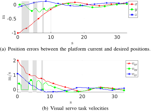
When the obstacle does not violate the inflation radius, the safety task becomes deactivated and the other subtasks can regain access to the previously blocked DoF. Fig. 3(a) shows how the servoing task is elusive during the first 10 seconds of the simulation when the obstacle is present, but is accomplished afterwards when the obstacle is no longer an impediment to the secondary task. 

Ja q̇a = R c b Ja q̇a, (11)with Rcb the rotation matrix of the body frame with respect to the camera frame, and where vcq corresponds to the velocity of the quadrotor expressed in the camera framevcq = R c b[ νbq + ω b q × rbcωbq] = [ Rcb −Rcb [ rbc ] ×0 Rcb] vbq, (12)with rbc(qa) the distance vector between the body and camera frames, and vbq = [νqx, νqy, νqz, ωqx, ωqy, ωqz]> the velocity vector of the quadrotor in the body frame. 

for the primary task the authors can substitute Eq. 21 into Eq. 20, giving σ̇0 = Λ0σ̃0, which for a defined main task error σ̃0 = σ∗0 − σ0 and σ∗0 = 0, the asymptotic stability is proven with L̇ = −σT0 Λ0σ0. 

By denoting with JI , JS , JG and JL theJacobian matrices of the above-mentioned tasks, the desired system velocity can be written as followsq̇ = J#I σ̃I + NI J # S ΛSσ̃S + NI|S J + G σ̃G+NI|S|G J + L σ̃L − JI|S|G|L$, (30)where NI , NI|S , NI|S|G are the projectors of the safety, the visual servoing and of the center of gravity tasks, which are defined asNI = (I− J#I JI) (31a) NI|S = (I− J+I|S JI|S) (31b) NI|S|G = (I− J+I|S|G JI|S|G) , (31c)with JI|S and JI|S|G the augmented Jacobians computed as in Eq. 27. 

The sum of normalized distances of the position of the i-th joint to its desired configuration is given bym∑ i=1 ( qai − q∗ai qai − qai )2 . (42)So their task function is selected as the squared distance of the whole arm joint configuration with respect to the desired oneσL = (qa − q∗a)>ΛL (qa − q∗a), (43)where qa = [ qa1, . . . , qam ]> and q a = [ q a1 , . . . , q am ]> are the high and low joint-limit vectors respectively, and ΛL is a diagonal matrix whose diagonal elements are equal to the inverse of the squared joint limit rangesΛL = diag((qa1 − qa1) −2, . . . , (qam − qam) −2). (44) 

The generalization of Eq. 23 to the case of η prioritized subtasks isq̇ = J+0 Λ0σ̃0 + η∑ i=1 N0|...|i−1J + i Λiσ̃i − J0|...|η$ (24)with the recursively-defined compensating matrixJ0|...|η = N0|...|i−1J + i Ji +