
All figures (12)

Fig. 4. Control quality evaluation by co-simulation of Matlab/Simulink and a SystemC-based virtual prototype. The coupling is achieved via an S-function that synchronizes the simulations. ![Fig. 5. A schematic view of the proposed co-simulation which follows the generic continuous/discrete synchronization model introduced in [23]. The Matlab/Simulink simulator solves the plant model at each simulation step. For each sampling time τi, the Matlab/Simulink simulation delivers the system state x(τi) and forwards it to the virtual prototype simulated in SystemC. The virtual prototype updates the control vector u(τi) and determines the delay di which are forwarded back to the Matlab/Simulink simulation.](/figures/fig-5-a-schematic-view-of-the-proposed-co-simulation-which-22kzzh0q.png)
Fig. 5. A schematic view of the proposed co-simulation which follows the generic continuous/discrete synchronization model introduced in [23]. The Matlab/Simulink simulator solves the plant model at each simulation step. For each sampling time τi, the Matlab/Simulink simulation delivers the system state x(τi) and forwards it to the virtual prototype simulated in SystemC. The virtual prototype updates the control vector u(τi) and determines the delay di which are forwarded back to the Matlab/Simulink simulation. ![Fig. 6. A simplified vehicle model based on the Quarter Car Model [24] is used here as the plant. This model assumes the vehicle has four identical wheels and the surface conditions of road stay static. The co-simulation begins with 50m/s as the initial velocity of the vehicle, followed by a full brake. The vehicle runs on wet road surface.](/figures/fig-6-a-simplified-vehicle-model-based-on-the-quarter-car-e0u96b8t.png)
Fig. 6. A simplified vehicle model based on the Quarter Car Model [24] is used here as the plant. This model assumes the vehicle has four identical wheels and the surface conditions of road stay static. The co-simulation begins with 50m/s as the initial velocity of the vehicle, followed by a full brake. The vehicle runs on wet road surface. 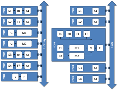
Fig. 8. The Brake-by-Wire system is mapped to two different architectures comprising of a FlexRay bus and seven ECUs or a CAN bus and five ECUs. 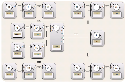
Fig. 7. The executable actor-based specification of the brake-by-wire system. The two main actors M1, M2 (redundant modeling) are responsible for computing candidate brake force and force feedback values, respectively. The final values applied to the four individual wheels are selected by a voter V actor. The four wheel actors RL, RR, FL, FR compute corrected brake forces to satisfy the ABS functionality. Sensors S1-S4 monitor wheel speeds and actuators A1-A4 apply brake forces to the wheels. The force applied to the brake pedal and its position are sampled via P1, P2. Actuator F applies the feedback force to the brake pedal. 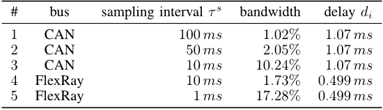
TABLE I SELECTED SYSTEM IMPLEMENTATIONS FOR THE BRAKE-BY-WIRE USE CASE. ![Fig. 9. Evaluation of the wheel rotational speed over time [s] using cosimulation to highlight the ABS functionality.](/figures/fig-9-evaluation-of-the-wheel-rotational-speed-over-time-s-3qyr9ukt.png)
Fig. 9. Evaluation of the wheel rotational speed over time [s] using cosimulation to highlight the ABS functionality. 
Fig. 1. During system design at ESL, a behavioral model termed executable specification and a component library are transformed to an exploration model. This model is employed during Design Space Exploration (DSE) to synthesize implementation candidates and evaluate them to quantify design objectives and investigate design constraints. DSE delivers a set of highquality implementation candidates from which the designer choses the best trade-off as the system-level implementation for subsequent design phases. 
Fig. 2. Visual representation of an actor, which sorts input data according to its algebraic sign. The actor consists of one input port i1 and two output ports o1 and o2. Transitions are depicted as directed edges. Each transition is annotated with an activation pattern, a boolean expression which decides if the transition can be taken, and an action (e. g. fpositive, fnegative) can be executed if the transition is taken. ![Fig. 11. Evaluation of the application-specific constraint slip over time [s] using co-simulation.](/figures/fig-11-evaluation-of-the-application-specific-constraint-134spzie.png)
Fig. 11. Evaluation of the application-specific constraint slip over time [s] using co-simulation. ![Fig. 10. Evaluation of the application-specific control quality metric braking distance over time [s] using co-simulation.](/figures/fig-10-evaluation-of-the-application-specific-control-fz4trlid.png)
Fig. 10. Evaluation of the application-specific control quality metric braking distance over time [s] using co-simulation. 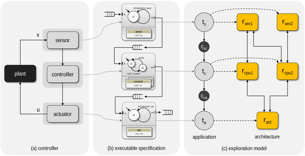
Fig. 3. Shown is (a) a typical controller in the state space model. Its proposed transformation into an executable specification, see (b), is depicted by dotted edges. From the executable specification, the desired exploration model, see (c), can automatically be derived as well. The resulting application consists of three tasks with a sensor task ts modeling the sensor, a control task tc modeling the controller including the input vector, and an actuator task ta modeling the actuator. A platform architecture graph is depicted in the exploration model as well, consisting of two different sensors suitable to carry out the sensor task, two CPUs suitable to execute the control task, and an actuator to implement the actuator task. The possible mapping of tasks to resources is depicted by the dashed edges.

![Fig. 5. A schematic view of the proposed co-simulation which follows the generic continuous/discrete synchronization model introduced in [23]. The Matlab/Simulink simulator solves the plant model at each simulation step. For each sampling time τi, the Matlab/Simulink simulation delivers the system state x(τi) and forwards it to the virtual prototype simulated in SystemC. The virtual prototype updates the control vector u(τi) and determines the delay di which are forwarded back to the Matlab/Simulink simulation.](/figures/fig-5-a-schematic-view-of-the-proposed-co-simulation-which-22kzzh0q.webp)
![Fig. 6. A simplified vehicle model based on the Quarter Car Model [24] is used here as the plant. This model assumes the vehicle has four identical wheels and the surface conditions of road stay static. The co-simulation begins with 50m/s as the initial velocity of the vehicle, followed by a full brake. The vehicle runs on wet road surface.](/figures/fig-6-a-simplified-vehicle-model-based-on-the-quarter-car-e0u96b8t.webp)


![Fig. 9. Evaluation of the wheel rotational speed over time [s] using cosimulation to highlight the ABS functionality.](/figures/fig-9-evaluation-of-the-wheel-rotational-speed-over-time-s-3qyr9ukt.webp)


![Fig. 11. Evaluation of the application-specific constraint slip over time [s] using co-simulation.](/figures/fig-11-evaluation-of-the-application-specific-constraint-134spzie.webp)
![Fig. 10. Evaluation of the application-specific control quality metric braking distance over time [s] using co-simulation.](/figures/fig-10-evaluation-of-the-application-specific-control-fz4trlid.webp)

16 Jul 2012-