
All figures (12)
![Fig. 7 Axial flux magnetic coupling prototype [11],[12].](/figures/fig-7-axial-flux-magnetic-coupling-prototype-11-12-4zwb9g07.png)
Fig. 7 Axial flux magnetic coupling prototype [11],[12]. 
Fig. 1 Topologies of rotating magnetic couplings (p=6). ![TABLE I DIMENSIONS OF THE CONSTRUCTED MAGNETIC COUPLING [11],[12]](/figures/table-i-dimensions-of-the-constructed-magnetic-coupling-11-6cs62iwn.png)
TABLE I DIMENSIONS OF THE CONSTRUCTED MAGNETIC COUPLING [11],[12] 
Fig. 8 Error on the torque prediction vs. the numbers of harmonics N and V. 
Fig. 2 Dimension of the permanent magnets of an axial flux coupler topology 𝜑 = 0 (iron yokes not shown). 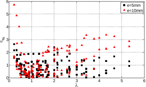
Fig. 10 Error on the torque calculation between the analytical expression (linearized geometry) and the 3D FE model (cylindrical topology). 
Fig. 9 Static torque of the magnetic coupling obtained with several methods in use - (18) used with N=V=20. 
Fig. 4 Domains and equations in the plan (x,z). 
Fig. 5 Magnetization Mz as a function of x and y (domain I). 
Fig. 3 Dimensions of one magnet pole after linearization (axis of rotation, located at 𝑦 = −𝑅𝑚𝑒𝑎𝑛 not shown). 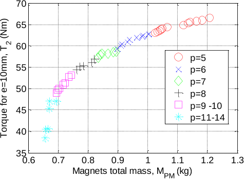
Fig. 11 Pareto front: Torque T2 vs. PMs mass MPM. 
Fig. 6 Equivalent surface charge density for a rectangular permanent magnet.
![Fig. 7 Axial flux magnetic coupling prototype [11],[12].](/figures/fig-7-axial-flux-magnetic-coupling-prototype-11-12-4zwb9g07.webp)

![TABLE I DIMENSIONS OF THE CONSTRUCTED MAGNETIC COUPLING [11],[12]](/figures/table-i-dimensions-of-the-constructed-magnetic-coupling-11-6cs62iwn.webp)


