
All figures (21)
 Figure 12. Undulator spectrum through the 120th harmonic integrated over the emittance-defined angular aperture of the fundamental.
 Table 4. Parameters of an undulator optimized for 8.3 keV photon energy
 Figure 2. Wavelength chirp and selection with a multi-layer
 Table 6. Some of the electron bunch parameters and the main properties of the spontaneous radiation are listed. The parameters of an alternative option of producing ultra-short pulses via time slicing with multi-layers (discussed in Section 2-i) are also listed in Table 6 and are indicated with a *.
 Figure 10. Radiation far-field target geometry in normalized angle space.
 Figure 8 Vertical photon beam parameters vs. vertical electron β-function. σp,hutch is for αe-= βe-/D.
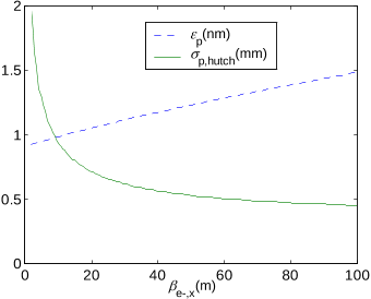 Figure 7 Horizontal photon beam parameters vs. horizontal electron β-function. σp,hutch is for αe-= βe-/D
 Figure 14. Design, construction and commissioning stages.
 Figure 4. Layout of the magnetic chicane placed at the 9 GeV location of the linac.
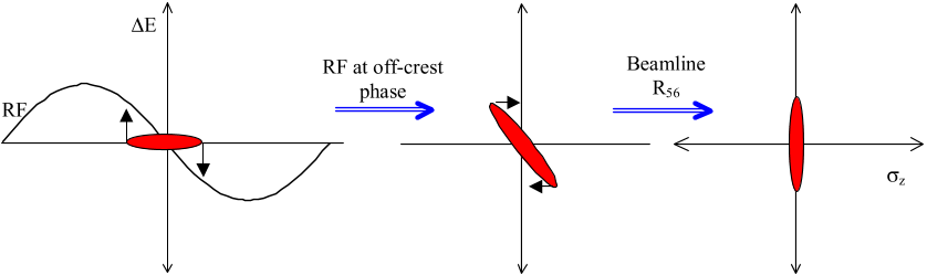 Figure 3. Schematic of ideal bunch compression where the bunch is given a correlated energy spread from head to tail followed by transport through a dispersive section whose path length varies with energy. The vertical axis represents the energy deviation, the horizontal axis the distance along the bunch.
 Figure 6. On the left: magnetic structure, with the larger blocks representing the NdFeB magnets and the vanadium permendur poles in between. The end termination is half pole + half magnet. On the right: The mechanical structure end view, with the strong-back frame surrounding the magnetic structure. The screws allow gauge blocks to be placed as spacers.
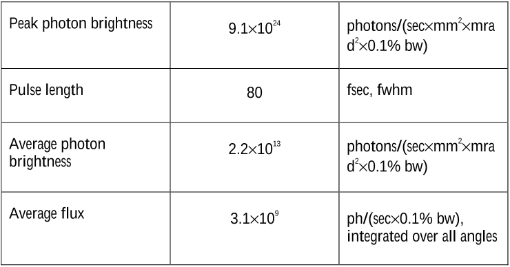 Table 1. Main SPPS radiation (8.3 keV) and electron beam (28 GeV) parameters
 Figure 1. Layout of the SPPS in the SLAC accelerator complex. The root-mean-square bunch length (rms) is shown at various stages.
 Figure 11. Full angle-integrated undulator spectrum through the 11th harmonic. The photon energy spread induced by the electron beam energy spread is 3% (rms).
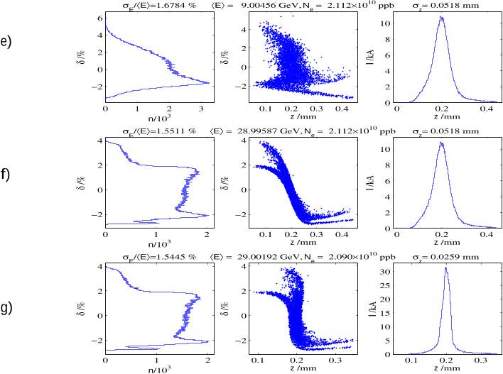 Figure 5. Compression process at various stages. The energy distribution is shown on the left, the phase space distribution is in the center, and the longitudinal distribution is on the right column: a) At damping ring extraction, b) after RTL acceleration, c) after RTL bends, d) at 9 GeV prior to compressor chicane, e) after compressor chicane, f) after linac at FFTB entrance, and g) after FFTB bends. Bunch head toward z < 0.
 Table 3. Main electron beam parameters.
 Table 7. Normal incidence peak energy loading for various materials at a distance of 34 m from the undulator end (location of the first optical element).
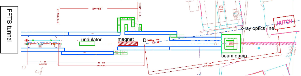 Figure 13. Layout of the x-ray optics transport system and experimental hutch. The magnet downstream of the undulator vertically deflects the electron beam onto the beam dump. The x-ray beam is deflected at the point indicated by “D” and taken to the experimental hutch outside the FFTB tunnel.
 Table 2. Radiation characteristics of the SPPS and other ultra-fast x-ray facilities.
 Table 5. Electron and photon beam envelope parameters
 Figure 9. Optics of the electron transport system to the undulator: β-functions (top curves) and dispersion. The horizontal axis is the distance in meters. QTEST denotes the quadrupole to be added to the line prior to the undulator.


