
All figures (16)
 Fig. 12. Chip micrograph.
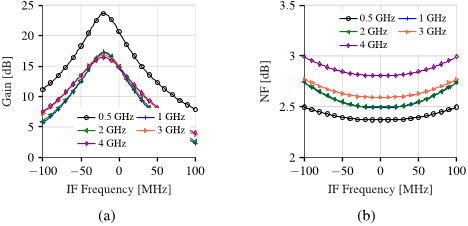 Fig. 7. (a) Voltage gain and (b) noise figure post-layout simulation results of combined LNTA, mixer and first filtering stage.
 Fig. 1. The proposed receiver chain chain with the clock generator modules.
 Fig. 8. BPF 4/8 modified circuit with implemented cross-connected transconductors.
 TABLE II RECEIVER PERFORMANCE SUMMARY AND COMPARISON WITH OTHER HIF RECEIVERS
 Fig. 2. The proposed LNTA topology.
 Fig. 11. (a) The delay line, (b) Frequency divider-by-2, (c) logic circuit that creates the 25% non-overlapping clock, (d) latch, and (e) tristate inverter with a transmission gate.
 Fig. 10. (a) Normalized gain and (b) Noise figure of the standard and modified BPF 4x8 with |β| = 0.2.
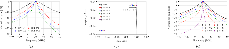 Fig. 9. (a) Transfer function of the BPF 4/4, 4/8, 4/12, 4/16. (b) Pole-zero mapping of the modified BPF 4/8 TF. (c) Transfer function of the modified BPF 4/8, where β is the cross-connection gain.
 Fig. 4. Transfer Function of the mixer and BPF when fs = 4G H z.
 TABLE I LNTA SIZING PARAMETERS
 Fig. 3. LNTA simulation results for temperature corners 27◦, 125◦, and −40◦ and process corners typical-typical (TT), fast-fast (FF), fast-slow (FS), slow-fast (SF), and slow-slow (SS).
 Fig. 14. (a) Noise Figure measurement results at the central frequency while the LO frequency is swept from 0.5 to 4 GHz. The (b) IIP3 and (c) IIP2 measurement results at 1 GHz LO.
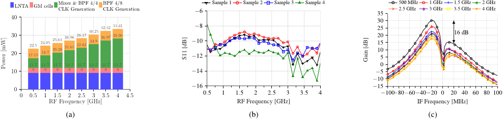 Fig. 13. (a) Power budget. (b) S11 measurement results from four different samples. (c) Gain measured at the I path at different RF frequencies, the legend shows the LO frequency at which the measurement has been performed.
![Fig. 5. (a) The passive mixer electrical model [19]. (b) The variation of the input impedance of the mixer with the LO frequency and (c) the value of CR programmed for each case. The comparison of the calculated and simulated input impedance of the mixer at (d) 500 MHz and (e) 1 GHz.](/figures/fig-5-a-the-passive-mixer-electrical-model-19-b-the-3sktp17s.png) Fig. 5. (a) The passive mixer electrical model [19]. (b) The variation of the input impedance of the mixer with the LO frequency and (c) the value of CR programmed for each case. The comparison of the calculated and simulated input impedance of the mixer at (d) 500 MHz and (e) 1 GHz.
Fig. 5. (a) The passive mixer electrical model [19]. (b) The variation of the input impedance of the mixer with the LO frequency and (c) the value of CR programmed for each case. The comparison of the calculated and simulated input impedance of the mixer at (d) 500 MHz and (e) 1 GHz.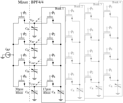 Fig. 6. Schematic of the passive mixer and the BPF 4/4.


![Fig. 5. (a) The passive mixer electrical model [19]. (b) The variation of the input impedance of the mixer with the LO frequency and (c) the value of CR programmed for each case. The comparison of the calculated and simulated input impedance of the mixer at (d) 500 MHz and (e) 1 GHz.](/figures/fig-5-a-the-passive-mixer-electrical-model-19-b-the-3sktp17s.webp)
