scispace - formally typeset
Open AccessJournal ArticleDOI

Detonation interaction with a diffuse interface and subsequent chemical reaction

Reads0
Chats0
TLDR
In this article, the authors investigated the interaction of a detonation with an interface separating a combustible from an oxidizing mixture, where the interface orientation and thickness with respect to the detonation wave have a profound effect on the outcome of the interaction.
Abstract
We have investigated the interaction of a detonation with an interface separating a combustible from an oxidizing mixture. The ethylene-oxygen combustible mixture had a fuel-rich composition to promote secondary combustion with the oxidizer in the turbulent mixing zone that resulted from the interaction. Diffuse interfaces were created by the formation of a gravity current using a sliding valve that initially separated the test gas and combustible mixture. Opening the valve allowed a gravity current to develop before the detonation was initiated. By varying the delay between opening the valve and initiating the detonation it was possible to achieve a wide range of interface conditions. The interface orientation and thickness with respect to the detonation wave have a profound effect on the outcome of the interaction. Diffuse interfaces result in curved detonation waves with a transmitted shock and following turbulent mixing zone. The impulse was measured to quantify the degree of secondary combustion, which accounted for 1–5% of the total impulse. A model was developed that estimated the volume expansion of a fluid element due to combustion in the turbulent mixing zone and predicted the resulting impulse increment.

read more

Content maybe subject to copyright    Report

D.H. Lieberman · J.E. Shepherd
Detonation Interaction with a Diffuse Interface and Subsequent
Chemical Reaction
Received: date / Accepted: date
Abstract We have investigated the interaction of a deto-
nation with an interface separating a combustible from an
oxidizing mixture. The ethylene-oxygen combustible mix-
ture had a fuel-rich composition to promote secondary com-
bustion with the oxidizer in the turbulent mixing zone that
resulted from the interaction. Diffuse interfaces were cre-
ated by the formation of a gravity current using a sliding
valve that initially separated the test gas and combustible
mixture. Opening the valve allowed a gravity current to de-
velop before the detonation was initiated. By varying the de-
lay between opening the valve and initiating the detonation
D.H. Lieberman
Graduate Aeronautical Laboratories, California Institute of Technol-
ogy, Pasadena, CA USA
Tel.: +626-437-3192
Fax: +310-754-2799
E-mail: dlieberman@exponent.com Present address: Exponent Fail-
ure Analysis Associates, Los Angeles, CA USA
J.E. Shepherd
Graduate Aeronautical Laboratories, California Institute of Technol-
ogy, Pasadena, CA USA E-mail: joseph.e.shepherd@caltech.edu
it was possible to achieve a wide range of interface condi-
tions. The interface orientation and thickness with respect to
the detonation wave have a profound effect on the outcome
of the interaction. Diffuse interfaces result in curved detona-
tion waves with a transmitted shock and following turbulent
mixing zone. The impulse was measured to quantify the de-
gree of secondary combustion, which accounted for 1-5%
of the total impulse. A model was developed that estimated
the volume expansion of a fluid element due to combustion
in the turbulent mixing zone and predicted the resulting im-
pulse increment.
Keywords Detonation · diffuse interface · secondary
combustion
1 Introduction
When a detonation wave propagating in a gaseous combustible
mixture reaches a concentration boundary, a complex inter-
action results between the detonation and interface between
the two gases. The details of this interaction are dependent
D. Lieberman and J. E. Shepherd "Detonation interaction with a Diffuse Interface and Subsequent
Chemical Reaction" Shock Waves 16(6):421-430, 2007. Preprint, see journal for final version http://
dx.doi.org/10.1007/s00193-007-0080-3

2 D.H. Lieberman, J.E. Shepherd
on the mixture compositions, the relative geometry of the
detonation and interface, and the characteristic thickness of
the interface.
In the present study, the interface is a composition gra-
dient between the combustible and non-combustible mix-
tures. The thickness of the interface is determined by mixing
caused by fluid mechanical stirring and diffusion. We clas-
sified the extent of the mixing at the interface by comparing
the cell size of the detonation with the interface thickness. A
sharp interface occurs when the detonation cell size is much
greater than the interface thickness.
1
A diffuse interface, the
case of the present study, occurs when the detonation cell
width in the combustible gas is much less than the interface
thickness.
The geometry of a detonation propagating in a composi-
tion gradient can be divided into two main categories. The
first is when the detonation velocity is parallel to the direc-
tion of the gradient, and the second is when it is perpen-
dicular. In general, the composition gradient vector and the
detonation velocity vector are not parallel or perpendicular
but at some intermediate angle. The first case has been stud-
ied by numerous researchers investigating the transmission
and successful re-initiation of a detonation across a gap of
non-combustible gas ([3], [8], [15], [16]). Other work [7] has
examined detonation transmission to an inert gas or other
combustible mixture and subsequent reflection off of a rigid
1
We have studied this case and the results will be presented in a
companion paper.
end-wall. The current study will focus to a large extent on
the perpendicular or nearly-perpendicular case.
When the detonation propagation direction is perpendic-
ular to the mixture gradient, a curved detonation wave results
that ultimately decouples into a shock wave and turbulent
mixing zone (TMZ), shown in Fig. 1b. This is due in part to
the dependence of the detonation velocity on the equivalence
ratio. For a detonation modeled as an ideal one-dimensional
discontinuity with no affect of curvature on reaction zone
structure, the normal component of the curved wave will cor-
respond to the local Chapman-Jouguet detonation velocity.
There has been little work done on detonation propagation
perpendicular to a continuous composition gradient. Exper-
iments [10] were carried out that measured concentration
gradients made by diffusion and used soot foils to charac-
terize the detonation propagation. Other work [4] examined
concentration gradients in a numerical study to investigate
the possibility of a flame occurring in the incomplete com-
bustion products. Oblique detonations were observed [5] in
sharp interface experiments where various combustible mix-
tures were separated in parallel channels. It is possible for
combustion to occur in the turbulent mixing zone (TMZ) by
choosing a combustible mixture such that the combustion
products are incompletely oxidized. This allows further re-
actions to take place if the mixture downstream of the inter-
face contains an oxidizer [14]. The aim of the following dis-
cussion is to address the key physical issues that arise when
a detonation propagates in the direction normal to a concen-
tration gradient. Some of the main issues to be discussed are

Detonation Interaction with a Diffuse Interface and Subsequent Chemical Reaction 3
INTERFACE
6
#*
ENDWALL
([S
([S
([S
([S
([S
([S
`
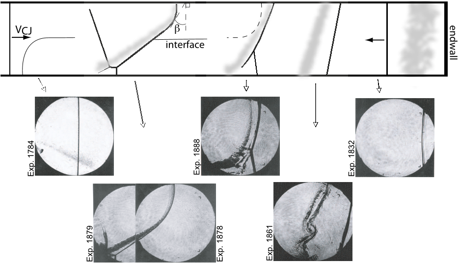
Fig. 1 The interaction of a detonation with a diffuse interface is illustrated with supporting observations from experimental images. A detonation
wave (a) interacts with the diffuse interface and forms a curved wave (b). Upon exiting the combustible mixture, the detonation decouples
completely resulting in a transmitted shock and TMZ (c) and (d). When the shock reaches the endwall it reflects (e) and interacts for a second
time with the interface.
the general shape of the detonation wave, and the decou-
pling of the shock wave and reaction zone. The presence of
secondary combustion between the partially oxidized deto-
nation products and oxidizer in the TMZ is also examined.
2 Experimental setup
The experiments were carried out using the GALCIT Deto-
nation Tube (GDT) [1,2], which is 7.3 m long with an inside
diameter of 0.280 m. It is connected to a 0.762 m long square
test section with inside dimensions of 0.15 m by 0.15 m. A
wave cutting device extends 1 m into the end of the GDT to
cut out a square section of the circular detonation front be-
fore entering the test section. A sliding valve assembly sep-
arates the ethylene-oxygen combustible mixture in the GDT
from the oxidizer or inert diluent in the test section during
the experimental preparation.
Figure 2 is a view of the test section illustrating the loca-
tion of the end flange of the GDT, the sliding valve assem-
bly, and the test section. Visualization for the experiments,
using a schlieren system [1], was made through an optical
viewport (BK7 or quartz windows) that could be arranged
in two separate positions. The first position is located 0.275
m downstream of the sliding valve and is referred to as port
1. The second viewport position is located 0.56 m down-
stream of the sliding valve (see Fig. 2) and is referred to as

4 D.H. Lieberman, J.E. Shepherd
port 2. The locations of the pressure transducers and a quartz
window on the end wall used for fluorescence imaging are
also shown. Fuel rich ethylene-oxygen mixtures occupied
the GDT, and either oxygen, nitrogen, or nitrous oxide occu-
pied the test section. The ethylene-oxygen equivalence ratio
Φ
= 2,2.5,3. The initial pressure and temperature for all ex-
periments were 15 kPa and 298 K, respectively. Detonations
'$4
3LIDING6ALVE!SSEMBLY
0RESSURE4RANSDUCERS
0,)&7INDOW
1UARTZ7INDOW
4EST3ECTION
"+7INDOW
00RESSURE
4RANSDUCER
0
0
0
Fig. 2 A schematic of the test section with the sliding valve assembly
and the end flange of the GDT.
were initiated in the GDT by discharging a 2
µ
F bank of
capacitors charged to 9 kV through a 0.16 mm copper wire.
Detonation velocities were measured to within 5% of the
Chapman-Jouguet speed. The cell sizes of the detonations
were measured using the soot foil technique [19] and were
in all cases below 5 mm.
The diffuse interface was made with a gravity current
(GC). The formation and propagation of the gravity current
was examined in the test section using acetone planar laser
induced fluorescence (PLIF) [12,17], and in a half-scale wa-
ter channel [20] to understand the early time development of
the GC, see Fig 3. The thickness of the diffuse interface,
δ
c
,
was estimated from the thickness of the region of vorticity
obtained from digital particle image velocimetry (DPIV) [9,
20] measurements from the water channel experiments and
then re-scaled for the gas phase experiments. In the PLIF ex-
periments, the combustible mixture in the GDT was replaced
with an acetone-helium mixture of matched density.
The sliding valve, actuated by a falling mass, was de-
signed to completely isolate both the combustible mixture
and test gas, as well as to open sufficiently fast to control
the formation of the gravity current. The sliding valve was
measured to open in 170 ms with an uncertainty of 10 ms.
The mass needed to achieve this opening time was 55 kg.
3 Results and discussion
The general description of this problem, shown as a schematic
in Fig. 1, is of a detonation wave propagating through a dif-
fuse interface. The diffuse interface is composed of ethylene-
oxygen with
Φ
= 2.5 above a layer of pure oxygen. The
two layer situation was created by allowing a long time to
elapse between the creation of the gravity current and det-
onation initiation (see discussion below). The sequence be-
gins with a detonation wave (a) prior to encountering the
diffuse interface. A curved detonation wave (b) results dur-
ing the interaction leading to a decoupled transmitted shock
and TMZ. As the detonation exits the gravity current, what
remains is a transmitted shock followed by the TMZ (c). The

Detonation Interaction with a Diffuse Interface and Subsequent Chemical Reaction 5
Fig. 3 Time sequence illustrating the development of a gravity current
using dye visualization. The gravity current head in the dense fluid (at
bottom of image) is propagating from right to left. The dark colored
fluid is the salt water solution and the clear fluid is de-ionized water.
The plate is completely withdrawn at 0.16 s.
shock wave and TMZ occupy a smaller axial distance than
the curved detonation wave with the distance between the
shock and TMZ (d) increasing with time. When the shock
reaches the endwall it reflects (e) and interacts with the inter-
face a second time. The reflected-shock-interface interaction
is not visible as it occurs in the space between the window
and the endwall. The complex interaction of the shock wave
with the lower experimental boundary Fig. 1b,c produces a
Mach reflection.
Gravity currents of various sizes were formed by vary-
ing the delay time, defined from the time the sliding valve
reaches the open position to the time when a detonation is
initiated in the GDT. The range of behavior is shown in
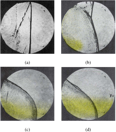
Fig. 4 where four separate experiments are shown at dif-
ferent stages of the gravity current development. In these
experiments the
φ
= 2.5 ethylene-oxygen combustible mix-
ture is colored yellow for visibility and flows below the less
dense nitrogen gas. Figure 4a is an image of a shock wave
followed by a TMZ. The delay time was 0 s, corresponding
to a planar interface, and consequently explains why there
is no gravity current visible on the overlay. This translates
to a leading shock wave that is for the most part perpen-
dicular to the top and bottom surface along with a reflected
trailing shock that is possibly due to slight imperfections in
the interface shape. As the gravity current grows, the wave
structure becomes more curved. Figure 4b shows the trans-
mitted shock, TMZ, and the location of the gravity current
before the combustible mixture was detonated with a delay
time of 1 s. The leading shock wave is curved with a Mach
stem at the top wall. Figure 4c shows the location of the
gravity current after a 2 s delay time and the presence of a
detonation propagating within 10% of the CJ velocity and
transverse waves visible just behind the detonation front at
the bottom of the figure. At a 3 s delay time, the curved det-
onation (Fig. 4d) looks similar to the detonation in Fig. 4c
except that the gravity current occupies half the height of the
test section thus changing the curvature of the leading wave.

Figures
Citations
More filters
Journal ArticleDOI

Modes of Detonation Wave Propagation in Water Vapor Concentration Gradients

TL;DR: In this paper, the authors investigate different combustion modes when a Chapman-Jouguet detonation propagates into H 2 O-diluted unburnt mixture through a composition gradient layer.
Journal ArticleDOI

Modeling detonation limits for arbitrary non-uniform concentration distributions in fuel–air mixtures

TL;DR: In this paper, a model is developed to generalize these classic detonation limits to consider arbitrary concentration distributions and is compared with experimental data for detonation propagation in non-uniform mixtures.
Journal ArticleDOI

Diaphragm effect on the detonation wave transmission across the interface between two mixtures

TL;DR: In this article, the effect of diaphragm thickness on the transmission of an incident detonation wave from a propane-oxygen mixture (donor) to a polypropane-air mixture (acceptor) was investigated.
Journal ArticleDOI

Numerical investigation of self-sustaining modes of 2D planar detonations under concentration gradients in hydrogen–oxygen mixtures

TL;DR: In this article, the self-sustaining modes of detonations in non-uniform mixtures for hydrogen and oxygen are numerically studied and the cellular structures and transmissions, failure and re-initiation mechanisms of detonation fronts are characterized.
Journal ArticleDOI

Proposed Vertical Expansion Tunnel

TL;DR: In this article, a vertical expansion tunnel was proposed to remove the diaphragm particulates in the test gas after its rupture, and the elimination of the wave system that is a result of a real secondary diaphrasm having a finite mass and thickness.
References
More filters
Journal ArticleDOI

Elements of gasdynamics

TL;DR: Elements of gasdynamics, Elements of gas dynamics, this paper, elements of gas dynamics, elements of gases, gas dynamism, and elements of dynamism.
Journal ArticleDOI

On errors of digital particle image velocimetry

TL;DR: In this article, a peak-normalization method was introduced to make the mean bias error negligible in comparison with the root-mean-square (RMS) error, and a peak compensation technique was also introduced to reduce the RMS error.

Turbulent Free Shear Layer Mixing and Combustion

TL;DR: In this article, the dependence of turbulent free-shear-layer growth, mixing, and chemical reactions are discussed, with the aid of some direct consequences deducible from large-scale organization of the flow as well as from some recent models.
Journal ArticleDOI

Experiments on the Richtmyer-Meshkov instability of an air/SF 6 interface

TL;DR: In this article, the authors performed flow visualization experiments of an impulsively accelerated plane interface between air and SF6 and found that the thin membrane, which forms the initially plane interface, has a significant influence on the initial growth rate of the interface thickness.

Turbulent free shear layer mixing and combustion

TL;DR: In this article, the dependence of turbulent free-shear-layer growth, mixing, and chemical reactions are discussed, with the aid of some direct consequences deducible from large-scale organization of the flow as well as from some recent models.
Related Papers (5)
Frequently Asked Questions (15)
Q1. What have the authors contributed in "Detonation interaction with a diffuse interface and subsequent chemical reaction" ?

The authors have investigated the interaction of a detonation with an interface separating a combustible from an oxidizing mixture. 

the shear layer displacement thickness changes from being negative to positive causing the surrounding fluid to be displaced and generating compression waves. 

A reference impulse of 1000 kg·m−1·s−1 obtained from impulse measurements at pressure transducer P4 is used to calculate the increment. 

The main consequence of the mixture composition gradient through the diffuse interface was to cause the detonation wave to curve: eventually the reaction zone decouples from the leading shock wave when the combustible mixture becomes sufficiently dilute. 

For a detonation modeled as an ideal one-dimensional discontinuity with no affect of curvature on reaction zone structure, the normal component of the curved wave will correspond to the local Chapman-Jouguet detonation velocity. 

The sliding valve, actuated by a falling mass, was designed to completely isolate both the combustible mixture and test gas, as well as to open sufficiently fast to control the formation of the gravity current. 

The rapid increase in induction time withdecrease in shock velocity results in the decoupling of the reaction zone from the shock and the formation of a gap between the transmitted shock and the turbulent mixing zone. 

By using a fuel-rich ethylene-oxygen combustible mixture and an oxidizing test gas, the authors were able to observe and quantify the effects of combustion inside the turbulent mixing zone. 

It is evident that the vorticity thickness of the interface is not uniform and exhibits a sinuous shape as a result of the turbulent flow structure present at the interface. 

In these experiments the φ = 2.5 ethylene-oxygen combustible mixture is colored yellow for visibility and flows below the less dense nitrogen gas. 

When the detonation propagation direction is perpendicular to the mixture gradient, a curved detonation wave results that ultimately decouples into a shock wave and turbulent mixing zone (TMZ), shown in Fig. 1b. 

The constant of proportionality C is varied from a value of 1 to 10 to account for interface growth after the shock reflection off the end-wall. 

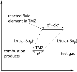
The velocity of the left (δu−p ) and right (δu+p ) edges of the fluid element are combined to obtain an expression for the growth rate of the fluid elementdx∗ dt = δu + p −δu−p . 

Visualization for the experiments, using a schlieren system [1], was made through an optical viewport (BK7 or quartz windows) that could be arranged in two separate positions. 

The details of this interaction are dependenton the mixture compositions, the relative geometry of the detonation and interface, and the characteristic thickness of the interface.