scispace - formally typeset
Open AccessJournal ArticleDOI

Modeling and Control of Magnetorheological Dampers for Seismic Response Reduction

Reads0
Chats0
TLDR
In this paper, a clipped-optimal control strategy based on acceleration feedback for controlling magnetorheological dampers is proposed to reduce structural responses due to seismic loads, and a numerical example, employing a newly developed model that accurately portrays the salient characteristics of the MR dampers, is presented to illustrate the effectiveness of the approach.
Abstract
Control of civil engineering structures for earthquake hazard mitigation represents a relatively new area of research that is growing rapidly. Control systems for these structures have unique requirements and constraints. For example, during a severe seismic event, the external power to a structure may be severed, rendering control schemes relying on large external power supplies ineffective. Magnetorheological (MR) dampers are a new class of devices that mesh well with the requirements and constraints of seismic applications, including having very low power requirements. This paper proposes a clipped-optimal control strategy based on acceleration feedback for controlling MR dampers to reduce structural responses due to seismic loads. A numerical example, employing a newly developed model that accurately portrays the salient characteristics of the MR dampers, is presented to illustrate the effectiveness of the approach.

read more

Content maybe subject to copyright    Report

Dyke, Spencer, Sain & Carlson August 1, 1996 1
Modeling and Control of Magnetorheological Dampers
for Seismic Response Reduction
S.J. Dyke,
1
B.F. Spencer Jr.,
2
M.K. Sain
3
and J.D. Carlson
4
1
Dept. of Civil Engrg., Washington University, St. Louis, MO 63130
2
Dept. of Civil Engrg. and Geo. Sci., Univ. of Notre Dame, Notre Dame, IN 46556
3
Dept. of Electrical Engrg., Univ. of Notre Dame, Notre Dame, IN 46556
4
Mechanical Products Division, Lord Corporation, Cary, NC 27511
Abstract
Control of civil engineering structures for earthquake hazard mitigation represents a relative-
ly new area of research that is growing rapidly. Control systems for these structures have unique
requirements and constraints. For example, during a severe seismic event, the external power to a
structure may be severed, rendering control schemes relying on large external power supplies in-
effective. Magnetorheological (MR) dampers are a new class of devices that mesh well with the
requirements and constraints of seismic applications, including having very low power require-
ments. This paper proposes a clipped-optimal control strategy based on acceleration feedback for
controlling MR dampers to reduce structural responses due to seismic loads. A numerical exam-
ple, employing a newly developed model that accurately portrays the salient characteristics of the
MR dampers, is presented to illustrate the effectiveness of the approach.
Introduction
The tragic consequences of the recent earthquakes in Kobe, Japan and in Los Angeles, Cali-
fornia have underscored, in terms of both human and economic factors, the tremendous impor-
tance of the way in which buildings and bridges respond to earthquakes. In the last decade,
significant effort has been devoted to the possibility of employing various control strategies in the
design of engineering structures to increase their safety and reliability against strong earthquakes
[20, 22–24, 39]. These control approaches are often termed protective systems and offer the ad-
vantage of being able to modify dynamically the response of a structure in a desirable manner.
Moreover, structural control systems can be an effective means by which existing structures can
be retrofitted or strengthened to withstand future seismic activity.
To date, active structural control has been successfully applied in over twenty commercial
buildings and more than ten bridges (during erection) [20]. Yet there are a number of serious chal-
lenges that remain before active control can gain general acceptance by the engineering and con-
struction professions at large. These challenges include: (i) reduction of capital cost and
maintenance, (ii) eliminating reliance on external power, (iii) increasing system reliability and ro-
bustness, and (iv) gaining acceptance of nontraditional technology by the profession. Semi-active

Dyke, Spencer, Sain & Carlson August 1, 1996 2
control strategies appear to be particularly promising in addressing a number of these challenges
[43].
Semi-active control devices potentially offer the reliability of passive devices, yet maintain
the versatility and adaptability of fully active systems. According to presently accepted defini-
tions, a semi-active control device is one which cannot input energy into the system being con-
trolled. Such devices typically have extremely low power requirements, which is particularly
critical during seismic events when the main power source to the structure may fail.
Various semi-active devices have been proposed which utilize forces generated by surface
friction or viscous/viscoelastic-plastic fluids to dissipate vibratory energy in a structural system.
Examples of such devices that have been considered for civil engineering applications include:
variable orifice dampers [9, 26, 29, 34, 36, 38], controllable friction braces [1, 10], controllable
friction isolators [19], variable stiffness devices [27], and electrorheological (ER) dampers [2, 17,
18, 21, 30, 32]. The effectiveness of one semi-active control system employing a variable stiffness
system has already been proven in a low-rise building in Japan [28].
Magnetorheological (MR) dampers are new semi-active control devices that use MR fluids to
provide controllable dampers that are quite promising for civil engineering applications [8, 15,
42]. They offer highly reliable operation at a modest cost and can be viewed as fail-safe in that
they become passive dampers should the control hardware malfunction. This paper first presents a
recently developed model for a prototype MR damper [42] that has been studied in the Structural
Dynamics and Control / Earthquake Engineering Laboratory (http://www.nd.edu/~quake/) at the
University of Notre Dame. Then a clipped-optimal acceleration feedback control strategy is pro-
posed for controlling the MR damper. The effectiveness of the proposed algorithm and the useful-
ness of MR dampers for structural response reduction are demonstrated through a numerical
example employing a seismically excited three story model building.
MR Damper Behavior and Modeling
Magnetorheological fluids recently developed by the Lord Corporation [3–7] (see also http://
www.rheonetic.com/mrfluid/) have many attractive features, including high yield strength, low
viscosity and stable hysteretic behavior over a broad temperature range. MR fluids are the mag-
netic analogs of electrorheological (ER) fluids and typically consist of micron-sized, magnetically
polarizable particles dispersed in a carrier medium such as mineral or silicone oil. When a mag-
netic field is applied to the fluids, particle chains form, and the fluid becomes a semi-solid, exhib-
iting plastic behavior similar to that of ER fluids. Transition to rheological equilibrium can be
achieved in a few milliseconds, providing devices with high bandwidth. Additionally, the achiev-
able yield stress of modern MR fluids is in excess of 80 kPa, allowing for devices capable of gen-
erating large forces such as are required for full-scale installations. In fact, MR dampers with a
capacity of 20 tons have been designed, with testing to begin in the summer of 1996 [8]. More-
over, MR fluids can operate at temperatures from –40 to 150
o
C with only slight variations in the
yield stress. Consequently, devices based on MR fluids are viable candidates for installation in
both exterior civil infrastructure applications (e.g., bridges, towers, etc.) as well as enclosed appli-
cations (e.g., buildings, secondary systems, etc.).
To evaluate the potential of MR dampers in structural control applications and to take full ad-
vantage of the unique features of these devices, a model must be developed that can accurately re-
produce the behavior of the MR damper. A prototype MR damper has been considered, which
was obtained for evaluation from the Lord Corporation and is comprised of a fixed orifice damper

Dyke, Spencer, Sain & Carlson August 1, 1996 3
filled with an MR fluid [42]. The damper is 21.5 cm long in its extended position, and the main
cylinder is 3.8 cm in diameter. The main cylinder houses the piston, the magnetic circuit, an accu-
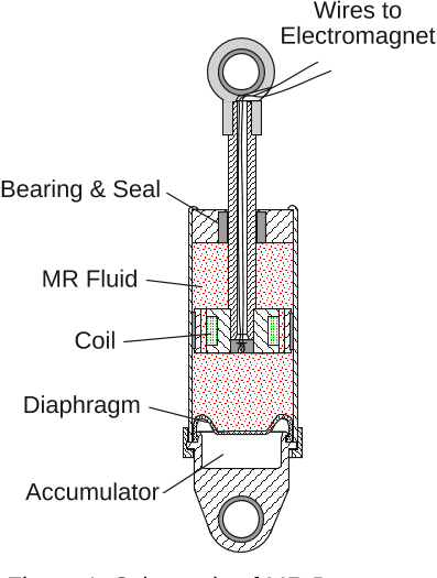
mulator and 50 ml of MR fluid, and the damper has a cm stroke. As shown in Fig. 1, the
magnetic field produced in the device is generated by a small electromagnet in the piston head.
The current for the electromagnet is supplied by a linear current driver running off of 120 V AC,
which generates a 0–1 amp current that is proportional to an applied DC input voltage in the range
0–3 V. The peak power required is less than 10 watts, which could allow the damper to be operat-
ed continuously for more than an hour on a small camera battery. Forces of up to 3000 N can be
generated with the device. The force is stable over a broad temperature range, varying less than
10% in the range of –40 to 150 degrees Celsius. The rise time (defined as the time required to go
from 10% to 90% of the final value) in the force generated by the MR damper during a constant
velocity test when a step in the voltage is applied to the current driver is approximately 8 msec.
This behavior is primarily due to the time the MR fluid in the damper takes to reach rheological
equilibrium and the time lag associated with the dynamics of driving the electromagnet in the MR
damper.
The response of the MR damper due to a 2.5 Hz sinusoid with an amplitude of 1.5 cm is
shown in Fig. 2 for four constant voltage levels, 0 V, 0.75 V, 1.5 V, and 2.25 V, being applied to
the current driver for the device. These voltages correspond to 0 A, 0.25 A, 0.5 A and 0.75 A, re-
spectively. Saturation of the MR effect begins in the tested device when the applied voltage is 2.25
V (0.75 A). Thus, attention is restricted to voltages between 0 and 2.25 V. The measured forces
are shown as a function of time in Fig. 2a, the force-displacement loops are shown in Fig. 2b, and
the force-velocity loops are shown in Fig. 2c. The force-displacement loops in Fig. 2b progress
along a clockwise path with increasing time, whereas the force-velocity loops in Fig. 2c progress
along a counter-clockwise path with increasing time. Note that the nonzero mean force produced
by the MR damper is due to the accumulator (see Fig. 1).
2.5±
Figure 1. Schematic of MR Damper.
AAA
AAA
AAA
AAAA
AAAA
AAAAA
AAAAA
AAAA
A
AA
A
A
AA
A
A
AA
A
A
AA
A
A
AA
A
A
AA
A
AAAA
AAAA
A
AA
A
A
AA
A
A
AA
A
A
AA
A
A
AA
A
AAAA
A
A
A
A
A
A
A
A
A
A
AAAA
AAAA
AAA
AA
AAAA
AAAA
AAAA
AAAA
A
AAAA
AAAA
A
AA
A
AAAA
AAAA
A
AA
A
AAAA
AAA
A
A
A
AAA
A
A
A
A
AA
AA
AA
AA
AA
AA
AA
AA
AA
AA
AA
AA
AA
AA
AA
AA
AA
AA
AA
A
A
A
AA
A
A
AA
MR Fluid
Accumulator
Diaphragm
Coil
Bearing & Seal
Wires to
Electromagnet

Dyke, Spencer, Sain & Carlson August 1, 1996 4
In Fig. 2, the effects of changing the magnetic field are readily observed. At 0 V the MR
damper primarily exhibits the characteristics of a viscous device (i.e., the force-displacement rela-
tionship is approximately elliptical, and the force-velocity relationship is nearly linear). However,
as the voltage increases, the force required to yield the fluid increases and produces behavior asso-
ciated with a plastic material in parallel with a viscous damper, i.e., Bingham plastic behavior
[37].
The simple mechanical idealizations of the MR damper depicted in Fig. 3 has been shown to
accurately predict the behavior of the prototype MR damper over a broad range of inputs [42].
The applied force predicted by this model is given by
(1)
or equivalently
(2)
where the evolutionary variable is governed by [45]
(3)
and
(4)
Figure 2. Experimentally Measured Force for 2.5 Hz Sinusoidal
Excitation with an Amplitude of 1.5 cm.
Time (sec)
Velocity (cm/sec)Displacement (cm)
Force (N)Force (N)
a) Force vs. Time
b) Force vs. Displacement
c) Force vs. Velocity
−2 −1 0 1 2
−1500
−1000
−500
0
500
1000
1500
−10 −5 0 5 10
−1500
−1000
−500
0
500
1000
1500
0 V
0.75 V
1.5 V
2.25 V
0.15 0.2 0.25 0.3 0.35 0.4 0.45 0.5 0.55
−1500
−1000
−500
0
500
1000
1500
f
f αzc
0
x˙ y˙()k
0
xy()k
1
xx
0
()+++=
fc
1
y˙ k
1
xx
0
()+=
z
z˙ γ x˙ y˙ zz
n 1
β x˙ y˙()z
n
Ax˙ y˙()+=
y˙
1
c
0
c
1
+()
---------------------
αzc
0
x˙ k
0
xy()++{}=

Dyke, Spencer, Sain & Carlson August 1, 1996 5
Here, the accumulator stiffness is represented by , the viscous damping observed at larger ve-
locities by . A dashpot, represented by , is included in the model to introduce the nonlinear
roll-off in the force-velocity loops that was observed in the experimental data at low velocities,
is present to control the stiffness at large velocities, and is the initial displacement of spring
associated with the nominal damper force due to the accumulator. By adjusting the parameters of
the model , and , one can control the shape of the hysteresis loops for the yielding element.
To account for the dependence of the force on the voltage applied to the current driver and the
resulting magnetic current, Spencer, et al. [42] have suggested
(5)
(6)
(7)
where is given as the output of a first-order filter given by
(8)
and is the commanded voltage sent to the current driver. Eq. (8) is necessary to model the dy-
namics involved in reaching rheological equilibrium and in driving the electromagnet in the MR
damper.
A constrained nonlinear optimization was used to obtain the 14 model parameters in Eqs. (1–
8). The optimization was performed using the sequential quadratic programming algorithm avail-
able in MATLAB [31]. Optimized parameters were determined to fit the generalized model to the
experimental data in a variety of tests. The resulting parameters are given in Table 1.
f
c
0
k
0
c
1
k
1
Figure 3. Simple Mechanical Model of the MR Damper.
Bouc-Wen
xy
k
1
c
0
c
1
k
0
x
0
k
1
γβ A
ααu() α
a
α
b
u+==
c
1
c
1
u() c
1a
c
1b
u+==
c
0
c
0
u() c
0a
c
0b
u+==
u
u˙ η uv()=
v

Citations
More filters
Proceedings ArticleDOI

Investigation of dissipativity for control of smart dampers via LMI synthesis

TL;DR: In this article, the effects of dissipativity on the performance of semi-active systems with smart dampers via linear matrix inequality (LMI) methods were investigated, and two dissipativity indices were proposed to quantify the dissipative nature of a force.
Proceedings ArticleDOI

Seismic response control of a large civil structure equipped with magnetorheological dampers

TL;DR: It is shown from the simulation that the proposed control system design framework is effective to mitigate seismically excited responses of a large building-MR damper system.
Journal ArticleDOI

Novel Spring-Buffered Variable Valve Train for an Engine Using Magneto-Rheological Fluid Technology

TL;DR: A novel variable valve actuation device that is compact and requires less energy was developed using magnetorheological (MR) fluid technology and indicated that the proposed MR valve could effectively provide functions of variable valve timing and variable valve lift by dynamically controlling the external current in the magnetic coil.
Journal ArticleDOI

H∞ control in the frequency domain for a semi-active floor isolation system

TL;DR: In this paper, a semi-active floor isolation system using rolling pendulum isolators and a magnetic-rheological damper was used to evaluate the effectiveness of the H676 ∞ control.
References
More filters
Journal ArticleDOI

Method for Random Vibration of Hysteretic Systems

TL;DR: In this paper, a new method of modeling and solution of a large class of hysteretic systems (softening or hardening, narrow or wideband) under random excitation is proposed.
Journal ArticleDOI

Active Structural Control: Theory and Practice

TL;DR: In this article, practical considerations control mechanisms optimization of actively controlled structures are considered, and an algorithm for actively controlled structure control algorithms is proposed, with a focus on the control mechanism optimization.

Phenomenological Model of a Magnetorheological Damper

TL;DR: In this article, a new model for controllable fluid dampers is proposed that can effectively portray the behavior of a typical magnetorheological damper and compared with experimental results for a prototype damper indicates that the model is accurate over a wide range of operating conditions.
Journal ArticleDOI

Commercial magneto-rheological fluid devices

TL;DR: Controllable magnetorheological (MR) fluid devices have reached the stage where they are in commercial production as discussed by the authors, and such devices are finding application in a variety of real world situations ranging...
Book

Elastic and inelastic stress analysis

TL;DR: In this article, Cartesian tensors have been used to model the behavior of engineering materials, including linear elastic behavior and nonlinear Viscoelastic behavior, in order to solve boundary value problems.
Related Papers (5)
Frequently Asked Questions (19)
Q1. What are the contributions mentioned in the paper "Modeling and control of magnetorheological dampers for seismic response reduction" ?

This paper proposes a clipped-optimal control strategy based on acceleration feedback for controlling MR dampers to reduce structural responses due to seismic loads. A numerical example, employing a newly developed model that accurately portrays the salient characteristics of the MR dampers, is presented to illustrate the effectiveness of the approach. 

Efforts are currently underway to investigate this possibility. 

At 0 V the MR damper primarily exhibits the characteristics of a viscous device (i.e., the force-displacement relationship is approximately elliptical, and the force-velocity relationship is nearly linear). 

The peak power required is less than 10 watts, which could allow the damper to be operated continuously for more than an hour on a small camera battery. 

Semi-active control devices potentially offer the reliability of passive devices, yet maintain the versatility and adaptability of fully active systems. 

They offer highly reliable operation at a modest cost and can be viewed as fail-safe in that they become passive dampers should the control hardware malfunction. 

To date, active structural control has been successfully applied in over twenty commercial buildings and more than ten bridges (during erection) [20]. 

Because the MR damper is attached between the first floor and the ground, its displacement is equal to the displacement of the first floor of the structure relative to the ground, i.e., in Eqs. (1–4). 

Because the semi-active system has the ability to vary its properties to more effectively control the structure, the clipped optimal controller performed better than both the passive-off and passive-on control systems. 

This behavior is primarily due to the time the MR fluid in the damper takes to reach rheological equilibrium and the time lag associated with the dynamics of driving the electromagnet in the MR damper. 

The rise time (defined as the time required to go from 10% to 90% of the final value) in the force generated by the MR damper during a constant velocity test when a step in the voltage is applied to the current driver is approximately 8 msec. 

If the magnitude of the force produced by the damper is smaller than the magnitude of the desired optimal force and the two forces have the same sign, the voltage applied to the current driver is increased to the maximum level so as to increase the force produced by the damper to match the desired control force. 

Various semi-active devices have been proposed which utilize forces generated by surface friction or viscous/viscoelastic-plastic fluids to dissipate vibratory energy in a structural system. 

The performance of the semi-active control system employing the MR damper was found to be modestly better in reducing peak displacements than that of the linear active controller, indicating that the semi-active control system is capable of not only approaching, but surpassing, the performance of linear active control system, while only requiring a small fraction of the power that is required by the active controller. 

When the MR damper is providing the desired optimal force (i.e., ), the voltage applied to the damper should remain at the present level. 

Because accelerometers can readily provide reliable and inexpensive measurement of accelerations at arbitrary points on the structure, development of control methods based on acceleration feedback is an ideal solution to this problem and will be presented subsequently. 

The structural measurements used for calculating the desired control force include the absolute accelerations of the three floors of the structure, and the displacement of the MR damper (i.e., ). 

According to presently accepted definitions, a semi-active control device is one which cannot input energy into the system being controlled. 

Assuming that the forces provided by the MR damper are adequate to keep the response of the primary structure from exiting the linear region, then the equations of motion can be written as(9)ż